Most phone mics are capable at low frequencies but have a high pass filter fitted in or after the mic preamp. Early IPhones, 3G for example, did not have an HPF as far as I know.
Phone mics are normally not that great at low frequencies. Btw. Do you run yours speakers without any additional xover?
I just did it to get a sense of what the distortion looks like, I know it's not a quality measurement. The fact that there's less distortion when I measure the the same test tone at the same amplitude from another speaker tells me the the distortion spectrum is probably mostly from the speaker, not the phone.
There's no additional crossover, just the active crossover. Both speakers are 7 ohms.
I did try the 100k resistors to ground and the 50R in the feedback loop but there was no difference. I think the switching spikes in the audio are so small it's no longer an issue (something like 10mv above the noise).
I also tried winding some toroid inductors today and there was an interesting result: the distortion was louder, but retained the same quality. I also forgot to change the capacitor, raising the Q. So it may be a garden variety inductor problem, or an underdamped filter issue. Also, woofers have a lot of inductance, so the impedance could be something like >40 ohms at >20khz. So all the filters I've built so far could have had a high Q.
The inductors I've tried so far, probably all with bad core materials in retrospect:
Bourns SRR1210M-470 (ferrite, http://www.mouser.com/pdfdocs/Bourns_SRR1210.pdf)
Bourns SRR1210M-220 (ferrite)
Jameco valuepro 22uH, 26A core material. I tried this because I'm near jameco. (http://www.jameco.com/Jameco/Products/ProdDS/371549.pdf)
23awg wire wound on 2x stacked T68-2 Amidon cores, 34 turns, 13uH. I tried this because the cores were sold nearby and tripath recommends the core material. Inductance is lower than desired and dcr higher than desired...
An externally hosted image should be here but it was not working when we last tested it.
Last edited:
Most phone mics are capable at low frequencies but have a high pass filter fitted in or after the mic preamp. Early IPhones, 3G for example, did not have an HPF as far as I know.
The phone is a OnePlus One. Not sure if it has a HPF on the input, but seems likely.
Ok, The woofer is ~30 ohms at 30khz, and ~35 ohms at 50khz.
The last output filter I tried was 470uH + 470nF, which would have a corner frequency of 34khz and a Q of 0.7, assuming the load was 7 ohms. But the load at 34khz is 30 ohms and the actual Q is more like 3.
When I tried the 13uH inductor I forgot to change the capacitor and the filter had a Q of something like 7.5 at 65khz!
I'm going to try something like 100uH + 100nF, see if that helps. That should bring the Q down to 0.94.
Ok, tried lowering the Q of the filter (220n + 96uH) using the bourns SRR1210 inductors and the distortion from the 200hz tone became almost inaudible in one channel.
At this point I'm suspecting the inductors, if that doesn't pan out I'll try cleaning up VDDA/VSSA
Ordered some wurth WE-PD series inductors, and some ICE components 1D10A-330M, will try those next.
At this point I'm suspecting the inductors, if that doesn't pan out I'll try cleaning up VDDA/VSSA
Ordered some wurth WE-PD series inductors, and some ICE components 1D10A-330M, will try those next.
Nice to hear that you made some efforts.
It will be nicer if I am able to find a solution to the problem.
Thanks again for all the thoughtful suggestions.
Alternatives to TOKO 16RHBP and 11RHBP
On the datasheet for the tda89XX NXP recommends toko 16RHBP inductors, which are not obtainable in small quantities (<1000).
Ti recommends 11RHBP for some of their designs. On TI's site someone asked for alternatives and Don Dapkus responded:
"I have seen some customers use Wurth inductors with some success.
Basically, you want your inductor to do two things:
1) have relatively constant L vs I - if L changes with current, then it will show up as THD
2) have a slow saturation point, or be rated so the inductor never approaches saturation --> otherwise, our chip my be damaged if you short the outputs and the current ramps up too quickly."
Neither of the inductors I tried have inductance vs. current listed in the spec sheet. Not sure how to identify a slow saturation point.
Some class d specific inductors I have identified:
-Wurth recommends their WE-PD series for Class D, available at mouser. Lots of values, current ratings, ~$2-$3 a pop.
Wurth Electronics WE-PD Shielded Power Inductors
-ICE components makes some higher current class d specific inductors in the 10-33uH range, up to 9.4A. pn ID10A, ID14A, ID17A, ID23A.
ICE Components Fixed Inductors | Mouser
-Coilcraft sells several class d specific inductors.
-Vishay just introduced a few economical dual class D inductors. IHLD3232HBER330M5A has 2x 33uH coils and is rated at 3.2A, for less than $3.
The max current rating is normally not at nominal L value.. :/
Good point.
On the recommended Toko 16RHBP:
-The 22uH part is good for 4.9A at "10% inductance reduction from the initial value, or coil temperature to rise by 40°C, whichever is smaller. (Reference ambient temperature 20°C)
-The 47uH 16RHBP is 3.4A
Wurth inductors have a nice chart in the datasheet. This 47uH inductor looks like it is good for ~4.8A with a 10% reduction in L, so might be a suitable replacement for the Toko part.
http://katalog.we-online.com/pbs/datasheet/7447709470.pdf
The Vishay and Ice inductors define Idc as "DC current through winding to cause a 40°C temperature rise at 25°C ambient." So maybe less useful.
Solved!
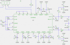
Ok, I finally found the solution: A bypass capacitor from VSSD (pin 24) to ground.
Bypass capacitors are shown on the datasheet for all power pins except VSSD, so I did not put one there. Also on the reference layout for the TDA8922 there is no bypass on VSSD.
On the datasheet for the TDA8920CTH I'm using VSSD is connected to VSSA. The old TDA8922 datasheet is more schizophrenic: On pgs 19 and 20 it's connected to VSSP (the rail) and on p29 it's connected to VSSA.
http://www.techlabs.by/downloads/articles/Logitech_Z_Cinema/tda8922.pdf
Thank you everyone for the suggestions.
Doctormord, a special thanks for taking the time to look more closely and make thoughtful, relevant suggestions.
NXP, f*** you for not bothering to respond to my support request.
Great work, well done. Do you think this is true for the TDA8950 series too?
The current TDA8950 VSSD data sheet from the NXP website, shows no decoupling for VSSD.
The current TDA8950 VSSD data sheet from the NXP website, shows no decoupling for VSSD.
Great work, well done. Do you think this is true for the TDA8950 series too?
The current TDA8950 VSSD data sheet from the NXP website, shows no decoupling for VSSD.
At TDA8950
pin# 17 is named VSSD
pin# 18 is named VSSA and directly connected to same power supply line which is decoupled by 220nF to GND.
BR, Toni
Attachments
At TDA8950
pin# 17 is named VSSD
pin# 18 is named VSSA and directly connected to same power supply line which is decoupled by 220nF to GND.
BR, Toni
Yes, but the pins are on opposite sides of the IC
Edit: pins are on opposite sides on the SMT package, not vertical you're using.
Last edited:
Great work, well done. Do you think this is true for the TDA8950 series too?
The current TDA8950 VSSD data sheet from the NXP website, shows no decoupling for VSSD.
Thanks.
It will probably help on the 8950, but it depends on how well or poorly it's laid out. It's easy enough to tack on a bypass cap and see.
With my layout the power trace goes thought two vias and across an area with no ground plane, so not the best arrangement.
I have a chinese pcb with the tda8922B and it has the same issue.
Last edited:
Yes, but the pins are on opposite sides of the IC
But not if you use the DIY friendly DBS23P package as I have done. 😉
My projects THD+N results are pretty close to the Datasheet - piano fuzz is still hearable at levels around 0.1% THD+N
(see: http://www.diyaudio.com/forums/clas...tda8950j-based-4-channel-power-amplifier.html)
BR, Toni
But not if you use the DIY friendly DBS23P package as I have done. 😉
My projects THD+N results are pretty close to the Datasheet - piano fuzz is still hearable at levels around 0.1% THD+N
(see: http://www.diyaudio.com/forums/clas...tda8950j-based-4-channel-power-amplifier.html)
BR, Toni
Ah, you're using the vertical package where VSSA and VSSD are adjacent to each other and can share a bypass capacitor. On the SMT package VSSA and VSSD are on opposite sides.
After adding the bypass cap the piano fuzz is 100% gone on my board.
Good job, least the frustration paid off 🙂. NXP should update datasheet, alteast add a note for the smd package. Finding 22uH+ inductors that has flat inductance/current graph up to 8-9+ A is not easy. Since the overcurrent protection for this chip is 9.2A the inductor should have saturation point above that value. TA2022 is in similar power class (overcurrent protection 7-8A) and they recommended 10A+ saturation point in case of fault. The TOKO 16RHBP 22uH has saturation @ 4.9A seems like a strange choice.
Two inductors that stays relatively flat to 8-9+ A is large-ish MM TXXX-2 (possible DCR, depending on size) & CC DO5040H (possible radiation issue), if you find more please post.
Two inductors that stays relatively flat to 8-9+ A is large-ish MM TXXX-2 (possible DCR, depending on size) & CC DO5040H (possible radiation issue), if you find more please post.
Last edited:
on class d, there is no passband switching transistion.
like class A the crossover point is the point of least distortion as the duty cycle of Fsw is 50%.
like class A the crossover point is the point of least distortion as the duty cycle of Fsw is 50%.
Excerpt from the 2002 Sep 25 datasheet where the TOKO 16RHBP inductors was utilized in reference circuit:
"Another factor which must be taken into account is the ripple current which will also flow through the output power switches. This ripple current depends on the inductor values which are used, supply voltage, oscillator frequency, duty factor and minimum pulse width. The maximum available output current to drive the load impedance can be calculated by subtracting the ripple current from the maximum repetitive peak current in the output pin, which is 7.5 A for the TDA8920TH."
Whats the formula for calculating ripple current? That could be useful to know more precise where the inductance/current graph optimally should be to be ruler-flat. I've used the lazy/dumb rule of thumb to be "around over-current protection".
The last production of TDA8920C has 9.2A over-current protection according to data-sheet (11 June 2009).
Tripaths recommendation on saturation point was to ensure graceful operation during fault condition like shortcut from what I can understand. Having saturation point above over-current protection value seems logical.
Excerpt from TA2022 data-sheet:
Output inductor selection is a critical design step. The core material and geometry of the output filter inductor affects the TA2022 distortion levels, efficiency, over-current protection, power dissipation and EMI output. The inductor should have low loss at 700kHz with 80Vpp. It should be reiterated that regardless of the systems maximum operating current, a 10A rating is required to ensure that peak current conditions will not cause the inductor to saturate. During a short circuit event the inductor current increases very quickly in a saturated core (see figure 6), compromising the current protection scheme. A 10A rating is sufficient to ensure that current increases through the inductor are linear, and provides a safety margin for the TA2022. There are two types of inductors available in the 10A range that offers some EMI containment: they are the toroidal type and the bobbin (shielded) type inductor.
pulexirritans: Do you have pictures of your board, would like to see it. You've got me interested in this chip.
- Status
- Not open for further replies.
- Home
- Amplifiers
- Class D
- Crosstalk / distortion / layout issues with NXP TDA8920CTH