I am working on a pair of 3 way speakers. cabinets have been designed, and im happy with my progress/ learning so far
I am following advice to learn how to make a nice simulation of the speaker. as apposed to just using the 3way crossover online calculator
I have finally found a nice program called box sim. it is free! and seems simple to use.
I am attempting to design a crossover for the speakers...
For the tweeter i had to make up 3 of the values because they where not in the spec sheet...
for qes:1
for qms:1
for vas 0.1
This provided a graph for the tweeter that was flat and the same as the spec sheet implyed
I set the drivers where they will be on the baffle, and had all other values entered
Here is the responce without my attempted crossover network
Looks good doesnt it? seems fairly flat, even without adding 5db attuention to the tweeter... (which i need to somehow learn how to do)
I copyed the values porvided by the online 3way crossover claculator 3-Way Crossover Designer / Calculator
Now. here is my attempted crossover. 3rd order,
Something is seriously wrong now 🙁
1 order also looked like junk but no where near as bad. the midrange is being calculated as rolling off from 500hz (see sim) this may be a error of the program as it doesnt match the spec sheet...😕
I am following advice to learn how to make a nice simulation of the speaker. as apposed to just using the 3way crossover online calculator
I have finally found a nice program called box sim. it is free! and seems simple to use.
I am attempting to design a crossover for the speakers...
For the tweeter i had to make up 3 of the values because they where not in the spec sheet...
for qes:1
for qms:1
for vas 0.1
This provided a graph for the tweeter that was flat and the same as the spec sheet implyed
I set the drivers where they will be on the baffle, and had all other values entered
Here is the responce without my attempted crossover network
An externally hosted image should be here but it was not working when we last tested it.
Looks good doesnt it? seems fairly flat, even without adding 5db attuention to the tweeter... (which i need to somehow learn how to do)
I copyed the values porvided by the online 3way crossover claculator 3-Way Crossover Designer / Calculator
Now. here is my attempted crossover. 3rd order,
An externally hosted image should be here but it was not working when we last tested it.
Something is seriously wrong now 🙁
1 order also looked like junk but no where near as bad. the midrange is being calculated as rolling off from 500hz (see sim) this may be a error of the program as it doesnt match the spec sheet...😕
here is the sim with a "borrowed", and slightly modified xover that uses the same woofer and midrange, and simular but different 27tffc tweeter
It looks much better. but i think the midrange and woofer xover point needs to be higher. which values should i change to acheve this? (i am afraid the midrange will move to much)
An externally hosted image should be here but it was not working when we last tested it.
It looks much better. but i think the midrange and woofer xover point needs to be higher. which values should i change to acheve this? (i am afraid the midrange will move to much)
Ok. What would really help me out is this
If somebody could circle out and label for me which parts are the impedence correction circets, that would be a good start for my ground up design. as the drivers are the same and the tweeter re is the same, this will save me alot of time working that bt out.
marking the parts that alter the xover frequencys would also be useful. even more ideally a labeled diagram explaining each part would be perfect for a newbie such as myself....
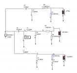
here is the origional scemetic , feel free to draw on it so i know whats what. thanks

If somebody could circle out and label for me which parts are the impedence correction circets, that would be a good start for my ground up design. as the drivers are the same and the tweeter re is the same, this will save me alot of time working that bt out.
marking the parts that alter the xover frequencys would also be useful. even more ideally a labeled diagram explaining each part would be perfect for a newbie such as myself....
here is the origional scemetic , feel free to draw on it so i know whats what. thanks
Hi,
Where did you get that x/o from ? It may be right and your simulation wrong.
It has no impedance correction parts, they are not needed.
Bass unit has a 2nd order electrical lowpass. Mid unit is 2nd order electrical
low pass and high pass. The tweeter 3rd order electrical. Resistors are for
level matching and a couple of them tweak filter functions.
rgds, sreten.
Boxsim AFAIK only works well with its database of Visaton drivers.
http://sites.google.com/site/undefinition/diy (see if nothing else, the excellent FAQs)
http://techtalk.parts-express.com/showthread.php?t=219617
http://www.zaphaudio.com
http://www.zaphaudio.com/ZA5/
http://audio.claub.net/Simple Loudspeaker Design ver2.pdf
http://www.rjbaudio.com/Audiofiles/FRDtools.html
http://web.archive.org/web/20090902124715/http://geocities.com/woove99/Spkrbldg/DesigningXO.htm
http://www.rjbaudio.com/
http://web.archive.org/web/20090902202231/http://geocities.com/woove99/Spkrbldg/
http://speakerdesignworks.com/
http://www.htguide.com/forum/showthread.php4?t=28655
http://www.deadwaxcafe.com/vzone/david/david.htm
http://www.troelsgravesen.dk/Diy_Loudspeaker_Projects.htm
http://www.humblehomemadehifi.com/download.html
http://www.quarter-wave.com/
http://www.frugal-horn.com/
http://www.linkwitzlab.com/
http://www.musicanddesign.com/
Great free SPICE Emulator : http://focus.ti.com/docs/toolsw/folders/print/tina-ti.html
Last edited:
Thanks for that information Sreten.
The xover was from a project with the same drivers as mine, with simular tweeter, as formentioned. i think t was a german builder, he had a build thread on a german site, and im sure he also posted his final project on here. i am trying hard to find it now
The xover was from a project with the same drivers as mine, with simular tweeter, as formentioned. i think t was a german builder, he had a build thread on a german site, and im sure he also posted his final project on here. i am trying hard to find it now
Last edited:
been googling round in circles for a hour or so. cannot find it anywhere, have to rethink this.
I was happy when i found Boxsim, because i finally saw a way to design the crossover. as you can see its sim of a 3rd order crossover was a desaster, looked more like a tuning fork that a responce plot... so even if i ditch the program i carnt risk just using the 3-Way Crossover Designer / Calculator just incase the sim was true?
i need a different approach then. im just not sure where to begin. to be honest i thought crossovers where a simple affair that worked as predicted etc. now i know that is not true
as this is my first ever xover, it needs to be as simple and effective as possable, fine tuning can and will probubly need o be done later. drivers centers will be acoustically alined. i was opting for 500hz and 3000hz as my xover points, but not i feel 500 and 2500 may be better.
what do i do first?
Last edited:
Hi,
See the FRDtools links in the list I posted for alternative tools.
There are several descriptions of using them effectively in the links.
I don't know boxsim, but with the right drivers files it should work.
Poor Man' is worth looking at.
The way to be confident with a simulator is simulate a well documented
design, e.g. one of Zaphs designs and get your results to agree with it.
You can't use that 3-way calculator, if you read the above
you will realise what a dreadfully misleading useless tool it is.
rgds, sreten.
FWIW aligning the the bass and mid acoustic centres is pointless,
due to the wavelengths involved at the x/o point. You can step the
the tweeter back, or like in most Zaph x/o's make it acoustically
slightly asymmetric, tilting the response back up at the x/o point.
Last edited:
It takes years to do a good sounding crossover.been googling round in circles for a hour or so. cannot find it anywhere, have to rethink this.
I was happy when i found Boxsim, because i finally saw a way to design the crossover. as you can see its sim of a 3rd order crossover was a desaster, looked more like a tuning fork that a responce plot... so even if i ditch the program i carnt risk just using the 3-Way Crossover Designer / Calculator just incase the sim was true?
i need a different approach then. im just not sure where to begin. to be honest i thought crossovers where a simple affair that worked as predicted etc. now i know that is not true
as this is my first ever xover, it needs to be as simple and effective as possable, fine tuning can and will probubly need o be done later. drivers centers will be acoustically alined. i was opting for 500hz and 3000hz as my xover points, but not i feel 500 and 2500 may be better.
what do i do first?
I think you already have the solution and ready to read the things below 🙂
It very important to read this :
http://www.diyaudio.com/forums/mult...ssover-assistance-request-15.html#post2862721
Do first : Buy a mic and a good software to have reliable measurement.
http://www.diyaudio.com/forums/mult...ssover-assistance-request-13.html#post2851628
You should understand, a crossover design depends on the geometry of the baffle.
An other project : http://www.diyaudio.com/forums/multi-way/140324-astasia-prject-3-ways-loudspeakers.html
2000/2500Hz yes the sound is better
see Denbret - DIY: Xover final Astasia SD
But I think you can use the PMS crossover as is it 😉
It is a good starting point.
It can take even more if we will allow plain errors.
Don’t you think that 15 mH a bit much for inductor in midrange network in your original design?
Don’t you think that 15 mH a bit much for inductor in midrange network in your original design?
Hi Waveinform
I've made some 3way seas speakers before as well. using 27tdc, mp14rcy mid and ca26rfx bass drivers. The midrange is an older type with rounded corners but I think the crossover may be of help still. I have padded the mid and treble a little as I like a little more bass trailing off slightly as it gets into the higher frequencies.
Regards
Simon
Attachments
I had a look at the poor mans strand xover as suggested. and for what its worth i ran a simulation with my drivers in (inaccurate) boxsim.
He does say he used the same tweeter as I, but he wasnt happy so he changed to a variant. Im not sure if he changed the network. However he still wasnt happy so he then moved the xover lower. So I reason that if he then swapped the tweeters back with the lower xover point, he still would have been happy
It appears the phase on the mid and tweeter need reversing with this design.
In a way i think it would be a good starting point for me, as the xover points are perfect and there is NO baffle step correction. also second order means lower price...
Obviously with a off the wack proram this simulation wont be perfectly accurate, if some one fancys running a "quick" sim in a better program i wont complain...
here is what i got
Any thoughts and opinions are welcome. also can anyone tell what the attuention amounts are on the tweeter and mid?
Thanks
ps: as a guide for the program i will run a sim of the pms with ITS drivers, to see how the plot matches up to his graph. as suggested
He does say he used the same tweeter as I, but he wasnt happy so he changed to a variant. Im not sure if he changed the network. However he still wasnt happy so he then moved the xover lower. So I reason that if he then swapped the tweeters back with the lower xover point, he still would have been happy
It appears the phase on the mid and tweeter need reversing with this design.
In a way i think it would be a good starting point for me, as the xover points are perfect and there is NO baffle step correction. also second order means lower price...
Obviously with a off the wack proram this simulation wont be perfectly accurate, if some one fancys running a "quick" sim in a better program i wont complain...
here is what i got
An externally hosted image should be here but it was not working when we last tested it.
An externally hosted image should be here but it was not working when we last tested it.
Any thoughts and opinions are welcome. also can anyone tell what the attuention amounts are on the tweeter and mid?
Thanks
ps: as a guide for the program i will run a sim of the pms with ITS drivers, to see how the plot matches up to his graph. as suggested
Last edited:
Attenuation : PMS speaker
27TFFC = 91dB ---> -2dB
MCA15 = 90dB ---> -2dB
I think you should experiment 😉 it's better to listen the effect of the crossover on the sound.
Do you have a schematic of the baffle ? Do you make a study of diffraction ?
27TFFC = 91dB ---> -2dB
MCA15 = 90dB ---> -2dB
I think you should experiment 😉 it's better to listen the effect of the crossover on the sound.
Do you have a schematic of the baffle ? Do you make a study of diffraction ?
Attenuation : PMS speaker
27TFFC = 91dB ---> -2dB
MCA15 = 90dB ---> -2dB
I think you should experiment 😉 it's better to listen the effect of the crossover on the sound.
Do you have a schematic of the baffle ? Do you make a study of diffraction ?
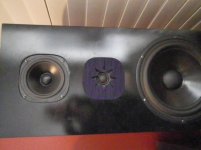
here is my "schemetic"..
An externally hosted image should be here but it was not working when we last tested it.
the parts shown in green are a possably and will be attatched to the sides of the mid/tweeter boxes, and will be anguler or curved.
so the baffle will be slight slimmer than the pms, the distance between mid and twee will be close to the same. and the distance between woofer and mid will be slightly less, but as its a larger driver, this is marginal.
drivers distances. tweetr mid gap 25mm approx. mid cassis to top of woofer cassis 10cm approx (by eye). if you need me to be more accurate i can draw a proper schemetic
my testing showed the tweeter to need more attuention than 2db, and the mid sounded fine as it was, but i would like to have the parts to hand to experement.
which resisters in the diagram are the ones i would need to alter the values of to altar attuetion? i want to be able to easly play with the attuention amounts with my test crossover
is a varable resister (lpad) a viable option? as levels seem to change atot depending on room and listening distance
OK your baffle should not have major diffraction issues.
As I remember this schematic does not work well with LPAD 😱
You should increase/decrease the value of R1011 ... You can go as high as 6.8 ohms with R1011 to adjust the tweeter level.
Be careful with the BR box of the CA26, it must be correctly tune.
As I remember this schematic does not work well with LPAD 😱
You should increase/decrease the value of R1011 ... You can go as high as 6.8 ohms with R1011 to adjust the tweeter level.
Be careful with the BR box of the CA26, it must be correctly tune.
OK your baffle should not have major diffraction issues.
As I remember this schematic does not work well with LPAD 😱
You should increase/decrease the value of R1011 ... You can go as high as 6.8 ohms with R1011 to adjust the tweeter level.
Be careful with the BR box of the CA26, it must be correctly tune.
Thanks for the resistor information im guessing 6.8 is high attuention so i have enougth to play with
in regards to box tuning.
tuning volume 90liters
dimentions 75x55x35external 70 50 30 internal
box volume 105liters
port tuning 27.5 (low note on piano)
square port... dimentions 36x10x10 internal 33.5x15x15external
port volume 7.54liters
left for bracing and driver 7.46liters
strait firing port 180rotation from woofer, inother words lower back of the box
material all 25mm mdf
(it in a thread called port question located here http://www.diyaudio.com/forums/multi-way/208556-port-question-8.html)
I was attemping not to merge topics but it seems with speakers it all factors together. I have atually started building the box, So unless there is a major 😱 error i dont want to alter much...🙂
I have been playing with the baffle sim, for both the mid and woofer, seems the fins on the mid box improve things slightly but there isnt much to quibble over
the bass section is fine as it is smooth to xover and should merge with room gain lower down... the mid may have a small 2db peek near1khz range.
here is a fairly accurate but not perfect sim
the light green line is the bass driver. the dark green line is the mid driver
An externally hosted image should be here but it was not working when we last tested it.

Here is the PMS xover, which i will borrow to base my design on if he doesnt mind..😉
Jerome69, you stated that there was 2db attuention on both the mid and tweeter...
R1011 is 3.3ohm the resistor on the tweeter
so logic says R2011 is 1ohm and the resistor on the midrange
how can they both be 2db. also in the program as a test i removed the value of the 3.3ohm resister and the tweeter level flew up 7db or so....?
What is the resister ohm to SPL attuention ratio?
Another thing i am wondering is about the phase (stay with me im learning here..)
all 3 xover slopes are all 12db/octave second order. however the polarity on the woofer has to be reversed. im just wondering why there is a 180 phase shift between the mid and woofer, but not between the mid and tweeter. just curious
An externally hosted image should be here but it was not working when we last tested it.
Jerome69, you stated that there was 2db attuention on both the mid and tweeter...
R1011 is 3.3ohm the resistor on the tweeter
so logic says R2011 is 1ohm and the resistor on the midrange
how can they both be 2db. also in the program as a test i removed the value of the 3.3ohm resister and the tweeter level flew up 7db or so....?
What is the resister ohm to SPL attuention ratio?
Another thing i am wondering is about the phase (stay with me im learning here..)
all 3 xover slopes are all 12db/octave second order. however the polarity on the woofer has to be reversed. im just wondering why there is a 180 phase shift between the mid and woofer, but not between the mid and tweeter. just curious
Last edited:
Looking at the sensitivity values between the ca22rfx and the PMS ca22rnx...
The rnx has a db or so less efficiency, than my ca22rfx, troelsgravesen probubly accounted for this by having slightly more attuention on his mid and tweeter networks?
im assuming changing these values doesnt mess with the rest of the crossover.
So i am equating that i my need to lessen the values of R1011 for the tweeter and R2011 for the mid...
How do i know what ohm of resistance equates to what spl reduction? should i just but a bunch of 0.5 resisters and play with them?
I carnt seem to find it in the forums, if someone knows or can point me to a good post i will be happy
Last edited:
Some responses ...
1. You should need to change the resistor values because a CA26 does 90dB/W/m
2. Count 1dB per ohms if you increase the tweeter resistor by 1 ohms, it decreases the level by 1dB.
3. Mid-woofer acoustic slopes is LR2, 12dB/oct. opposite polarity between them.
Mid-tweeter LR4, 24db/oct. same polarity
Hope this useful 😉
My boxes are comming along very nicely,  and im almost ready to order the crossover parts from europe audio.
I just have 3 small questions before i commence, if anyone can help
1)
Are jazen standard z caps fine? or should i use superiour z caps for atleast the mid and tweeter section? the pms xover seems to use the standard black ones
2)
Looking at the resisters in his picture, they are 10w
Poor Man'
Here are the resisters i think i should be using
MOX-10-3.90 - Jantzen metaloxide resistor 3.90R 10W 5% - Europe Audio
But is there any feesable reason not to use these?
Europe Audio • Resistors types • Ceramic 10W
and, most importently!
3)
I would like to be able to play around with various resistance on the tweeter, and possabily the midrage, I think i know which ones to alter.
What is the best way to test resistance values with the lowest cost factor,
Can i wire 2 in series to double the resistance from, say 0.5+0.5=1ohm?
If so i can buy an assortment of 2,1 and 0.5 ohm ones and just play around. Aan suggestions would be appreciated.
Thanks
and im almost ready to order the crossover parts from europe audio.I just have 3 small questions before i commence, if anyone can help
1)
Are jazen standard z caps fine? or should i use superiour z caps for atleast the mid and tweeter section? the pms xover seems to use the standard black ones
2)
Looking at the resisters in his picture, they are 10w
Poor Man'
Here are the resisters i think i should be using
MOX-10-3.90 - Jantzen metaloxide resistor 3.90R 10W 5% - Europe Audio
But is there any feesable reason not to use these?
Europe Audio • Resistors types • Ceramic 10W
and, most importently!
3)
I would like to be able to play around with various resistance on the tweeter, and possabily the midrage, I think i know which ones to alter.
What is the best way to test resistance values with the lowest cost factor,
Can i wire 2 in series to double the resistance from, say 0.5+0.5=1ohm?
If so i can buy an assortment of 2,1 and 0.5 ohm ones and just play around. Aan suggestions would be appreciated.
Thanks
I see cross cap type caps. The standard z should be a bit better.the pms xover seems to use the standard black ones
When in doubt, use 10W resistors. MOX are non inductive resistors so are better suited for crossovers.Here are the resisters i think i should be using
MOX-10-3.90 - Jantzen metaloxide resistor 3.90R 10W 5% - Europe Audio
But is there any feesable reason not to use these?
Europe Audio • Resistors types • Ceramic 10W
Just buy a set of cheap 5W resistors, and some alligator clips. So you'll be able to try different values on the fly. I did the same also for the caps (cheap bipolar). Once you find the correct value, spend the money on good parts.I would like to be able to play around with various resistance on the tweeter, and possabily the midrage, I think i know which ones to alter.
Ralf
- Status
- Not open for further replies.
- Home
- Loudspeakers
- Multi-Way
- Crossovers for my 3 way Seas speakers...