Hi All,
My first post here (other than my intro)!
I have spent the better part of the past few days going through the internet for crossover design tips and it seems as if it is a little bit of a dark art.
I've prototyped a speaker based on my requirements, built the boxes, got the drivers in and used a MiniDSP to try and find the sound of the type of crossover I am after. This lead me to settle on a 3rd order at 2.2k for both drivers, tweeter down 4db. It seems to give me the power handling I need for the tweeter because of the steeper slope and tames some of the breakup in the 10 inch driver I am trying to cross over (I know - a tricky task!).
Very quickly I have learned that I can't just plug those values into a crossover calculator and so have spent some time learning to use VituixCAD whilst using those calculator results as a jumping off point.
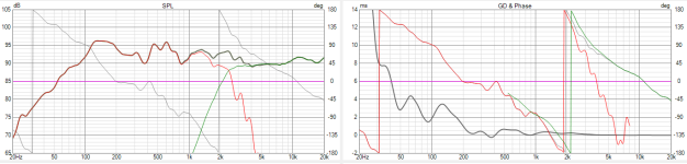
I have managed to get to a point where I am happy with the frequency response plot. The tweeter looks excellent, but the woofer is a bit wobbly - I think that is alright though, it sounds nice in real life.
I'm now at a point where I am on to the phase relationship and how a 3rd order can sometimes be tricky to wrangle.
I suddenly have realised that the phase does not line up properly, especially at the point where it seems to flip.
It looks as if I am about 30 degrees out at the crossover point.
My question is, how important is this in the reality of creating a crossover? Presumably as soon as you move off axis this phase response will change (which brings in a whole new dimension)?
My model is using actual values of components I can order so there isn't a massive amount of wiggle room.
Also as a bonus question, I'm guessing that moving the phase around is more than just about shifting component values until they are ideal? If I change the values of the components, I can never quite get it to show a frequency response I would like - it does shift quite a lot!
I know that the ideal situation is to buy lots of bits and try them out, but I am trying to get it as good as I can the first time round so that I don't have to reorder a whole bunch of stuff - but I do know that with time I'll have more of an inventory at my disposal!
Thank you all in advance!
My first post here (other than my intro)!
I have spent the better part of the past few days going through the internet for crossover design tips and it seems as if it is a little bit of a dark art.
I've prototyped a speaker based on my requirements, built the boxes, got the drivers in and used a MiniDSP to try and find the sound of the type of crossover I am after. This lead me to settle on a 3rd order at 2.2k for both drivers, tweeter down 4db. It seems to give me the power handling I need for the tweeter because of the steeper slope and tames some of the breakup in the 10 inch driver I am trying to cross over (I know - a tricky task!).
Very quickly I have learned that I can't just plug those values into a crossover calculator and so have spent some time learning to use VituixCAD whilst using those calculator results as a jumping off point.
I have managed to get to a point where I am happy with the frequency response plot. The tweeter looks excellent, but the woofer is a bit wobbly - I think that is alright though, it sounds nice in real life.
I'm now at a point where I am on to the phase relationship and how a 3rd order can sometimes be tricky to wrangle.
I suddenly have realised that the phase does not line up properly, especially at the point where it seems to flip.
It looks as if I am about 30 degrees out at the crossover point.
My question is, how important is this in the reality of creating a crossover? Presumably as soon as you move off axis this phase response will change (which brings in a whole new dimension)?
My model is using actual values of components I can order so there isn't a massive amount of wiggle room.
Also as a bonus question, I'm guessing that moving the phase around is more than just about shifting component values until they are ideal? If I change the values of the components, I can never quite get it to show a frequency response I would like - it does shift quite a lot!
I know that the ideal situation is to buy lots of bits and try them out, but I am trying to get it as good as I can the first time round so that I don't have to reorder a whole bunch of stuff - but I do know that with time I'll have more of an inventory at my disposal!
Thank you all in advance!
Attachments
You should measure each driver with the x-over, and display results like the sim you posted here.
I am trying to get as close as possible in a simulated environment before committing to buying the components needed. I'll definitely be measuring after the build but am more just looking for advice to point out if there is anything inherently (or sound ruiningly!) wrong with what I have so far so that I will need tweaks rather than a total overhaul.
I know unpredictability is part of the crossover design process but hopefully with the right design it will iron out any major creases!
I've measured in a DSP environment, but I'm guessing that won't mean much as electrical components will behave differently?
I know unpredictability is part of the crossover design process but hopefully with the right design it will iron out any major creases!
I've measured in a DSP environment, but I'm guessing that won't mean much as electrical components will behave differently?
It looks as if I am about 30 degrees out at the crossover point.
My question is, how important is this in the reality of creating a crossover?
what crossover? i.e. what is your acoustic target?
what crossover? i.e. what is your acoustic target?
I'm not sure I quite understand what you mean by acoustic target - other than just a general sound signature?
I'm happy with the measurements I've taken using an active DSP and essentially want to translate this to a passive crossover (or at least as close as I can)
So I guess my target is the same as that - 3rd order xover at 2.2k, tweeter at -4db. My question is not really so much to do with the frequency response, but more to do with whether the phase shift exhibited in the screenshot would in reality be problematic (assuming in reality it were to match that response).
I'm expecting to have to do some tweaking but am wondering if by these graphs it looks as if there is something inherently wrong in the design, or whether this is within tolerances of what would generally be considered to be a good performance
Hi,
When you said that you have measured, do you mean measured each speaker response (frequency/phase) with a calibrated mic? And did you measure the impedance of each speaker as well? Are these measurements being used in Vituix?
When you said that you have measured, do you mean measured each speaker response (frequency/phase) with a calibrated mic? And did you measure the impedance of each speaker as well? Are these measurements being used in Vituix?
More information is needed.
Measured woofer, tweeter, and sum, with the electronic x-over.
Measured woofer and tweeter raw.
Details of the passive x-over sim.
Details of active delays, or EQ.
Details of measurement setup.
The sim graph itself looks like it's OK, but details could affect the accuracy of the sim.
I would only trust gated measurements myself, but with the right setup, it doesn't matter.
No problem (not in the way you seem to be suggesting).. assuming it's correctly measured.It looks as if I am about 30 degrees out at the crossover point.
Also the woofer rolloff seems to be steeper than the tweeter. It may be OK.
If you want flat summation and best phase response you should be using 4th order Linkwitz-Riley, not any 3rd order.
Why don't you just use the mini DSP equipment as an active crossover?I'm happy with the measurements I've taken using an active DSP and essentially want to translate this to a passive crossover (or at least as close as I can)
I've been using analog active crossovers for 5 years now and would never go back to passive.
Yes, I understand passive is more convienient in terms of amps and cables, but the improvement in sound quaility and flexibility is really worth it.
Just my $0.02 FWIW.

The measurements I have are from the active setup using a calibrated mic and REW - just for frequency response.Hi,
When you said that you have measured, do you mean measured each speaker response (frequency/phase) with a calibrated mic? And did you measure the impedance of each speaker as well? Are these measurements being used in Vituix?
In terms of the actual speakers, I am using the manufacturers' spec sheets traced in VituixCAD - I know these can be suboptimal, but I don't have a DATS system or equivalent so I'll have to trust them for the time being!
I can take individual measurements of the drivers themselves in situ - the frequency response plot is similar to that in the image I attached, quite flat and then a roll off for the treble. The phase seems alright too - I do have a cap in front of the tweeter for protection which has seemed to introduce a bit of shift - I had to reverse polarity to avoid a null at the xover point.More information is needed.
Measured woofer, tweeter, and sum, with the electronic x-over.
Measured woofer and tweeter raw.
Details of the passive x-over sim.
Details of active delays, or EQ.
Details of measurement setup.
The sim graph itself looks like it's OK, but details could affect the accuracy of the sim.
I would only trust gated measurements myself, but with the right setup, it doesn't matter.
There are no active delays - just a very basic xover. These are speakers that will be ideally used not for critical listening but in a more ambient format so off axis response is tricky.
Measurement setup is a UMIK1 and REW for the time being - nothing to measure the drivers electrically as mentioned above
I'm trying to get most of the way there through the sim and then tweak if I need to at the end - mostly if I can actually hear any audible problems. I am comparing in a room with a system that comprises of Qual ESL2905s with a pair of REL stadium subs, and also a pair of Tannoy IIILZs as the B setup. I also have a smaller system of a pair of Focal Solo 6s and a homemade sub. I feel I have enough high quality real world varied reference points in those to get something together?
Excellent! Thank you - this is very interesting reading down to such a detailed level. I guess the takeaway is that we don't listen like an oscilloscope and that its about real world perceptible results! I did see a polar chard somewhere that had a basic layout of acceptable shifts in real world situations but I don't remember which thread it was on.
This is the answer I was expecting - I think in the real world I would use the active crossover, and if I were to make more speakers it would be my preference - it is so much easier! I'm running a pair of subs with these that are purely DSP. However, I want to learn what goes in to a passive crossover, I have already learned so much through this as an exercise. I also want to make something that is easier to integrate into other systems and can run easily off a normal amp.Why don't you just use the mini DSP equipment as an active crossover?
I've been using analog active crossovers for 5 years now and would never go back to passive.
Yes, I understand passive is more convienient in terms of amps and cables, but the improvement in sound quaility and flexibility is really worth it.
Just my $0.02 FWIW.
However, I do think slapping a Hypex on the back would save a lot of hassle!
Virtuix is a very good learning experience.
After you have a trace of the frequency response and impedance.
You would use that 0 degree trace to create a full space simulation on the baffle you plan to use.
In diffraction tool, which would give you off axis info as well.
Then in crossover designer you set the Z offset for each driver to account for the mounting position.
Tweeter considered listening position can stay at 0 but the woofer needs the Z distance set.
Or how close you will physically mount them in real life.
Close as possible is the answer, how close that is physically possible needs to be calculated.
Then set in the sim, so then your working with the actual phase relationship of the 2 drivers
Then overall phase will be correct, and then spend time with the filters.
You can load a 3 rd order filters from the library.
And be able to scroll the impedance and frequency.
This will choose/ calculate better coil/cap values. no external calculator needed.
Tweeter will need to be very large 1 1/4" to vaguely come close to working with a 10"
actually 8" is about the limit.
Will make sense once your in full space, on the baffle and see off axis responses generated by the diffraction tool.
Slight learning curve but will offer a lot of insight and make all the " theories" visible and make sense.
Thank you for the detailed run down, this is very helpful and realistic given the limitations I currently have!Virtuix is a very good learning experience.
After you have a trace of the frequency response and impedance.
You would use that 0 degree trace to create a full space simulation on the baffle you plan to use.
In diffraction tool, which would give you off axis info as well.
Then in crossover designer you set the Z offset for each driver to account for the mounting position.
Tweeter considered listening position can stay at 0 but the woofer needs the Z distance set.
Or how close you will physically mount them in real life.
Close as possible is the answer, how close that is physically possible needs to be calculated.
Then set in the sim, so then your working with the actual phase relationship of the 2 drivers
Then overall phase will be correct, and then spend time with the filters.
You can load a 3 rd order filters from the library.
And be able to scroll the impedance and frequency.
This will choose/ calculate better coil/cap values. no external calculator needed.
Tweeter will need to be very large 1 1/4" to vaguely come close to working with a 10"
actually 8" is about the limit.
Will make sense once your in full space, on the baffle and see off axis responses generated by the diffraction tool.
Slight learning curve but will offer a lot of insight and make all the " theories" visible and make sense.
Somehow I had no idea that Vituix has a library of filters... That certainly is an eye opener and I feel like a bit of a prong 🤦♂️
The tweeter is a 1 1/8th and the woofer is a pretty tight PA driver so it can cross quite high (the breakup is around 5k by the looks of things), it only working from ~80Hz and a sub will do the rest. It's the main part of my challenge to try to get the drivers to integrate properly, generally I wouldn't go above a 6.5. This is the reason for a 3rd order and the lower xover point at 2.2k.
However, in my initial testing on a DSP, I was very surprised at how good it sounds so far!
Breakup usually starts below the peak and vituixcad doesn't model breakup. If the 0 degree response is used, the peak will be overrepresented. Best to stay clear of the region without polar measurements.it can cross quite high (the breakup is around 5k by the looks of things),
If you want to start using the digital theoretical filters you can go back later and fit a circuit around it.that Vituix has a library of filters
click library tap

select passive for collection of passive filter blocks

Once you paste in the filter you want to work with.
Right click any component in that block and select tune block or ctrl T

Window will open you can change values by high lighting in blue
and adjust values with mouse scroll.
Z does not have to remain " 8 ohms" or the driver impedance
crossover points are often much different and the overall impedance
can be fine tuned likewise. Snap for values can be set to 20%
or once you get the filter you like, use real components close to the value.
Then of course can rebuild the filter with individual components
and match the values of series resistance according to manufactures data sheet.
Of the real components you plan on buying

You can click on components in the block and set values to snap to common ratings
and also for say a inductor set the DCR to what the manufacture lists in datasheet.
Use arrow keys to change values

select passive for collection of passive filter blocks
Once you paste in the filter you want to work with.
Right click any component in that block and select tune block or ctrl T
Window will open you can change values by high lighting in blue
and adjust values with mouse scroll.
Z does not have to remain " 8 ohms" or the driver impedance
crossover points are often much different and the overall impedance
can be fine tuned likewise. Snap for values can be set to 20%
or once you get the filter you like, use real components close to the value.
Then of course can rebuild the filter with individual components
and match the values of series resistance according to manufactures data sheet.
Of the real components you plan on buying
You can click on components in the block and set values to snap to common ratings
and also for say a inductor set the DCR to what the manufacture lists in datasheet.
Use arrow keys to change values
Last edited:
You are a legend! Thanks for the detailed run down, it's great that you can change whole blocks at one time. I was kind of just moving values around randomly and being confused, it's great to have a jumping off point built in. There are so many moving variables that it gets quite intimidating to start but I think I am getting there.
Are you going to show us the sim, and the measured woofer, tweeter, and sum, with the electronic x-over.?The measurements I have are from the active setup using a calibrated mic and REW - just for frequency response.
In terms of the actual speakers, I am using the manufacturers' spec sheets traced in VituixCAD - I know these can be suboptimal, but I don't have a DATS system or equivalent so I'll have to trust them for the time being!
I can take individual measurements of the drivers themselves in situ - the frequency response plot is similar to that in the image I attached, quite flat and then a roll off for the treble. The phase seems alright too - I do have a cap in front of the tweeter for protection which has seemed to introduce a bit of shift - I had to reverse polarity to avoid a null at the xover point.
There are no active delays - just a very basic xover. These are speakers that will be ideally used not for critical listening but in a more ambient format so off axis response is tricky.
Measurement setup is a UMIK1 and REW for the time being - nothing to measure the drivers electrically as mentioned above
I'm trying to get most of the way there through the sim and then tweak if I need to at the end - mostly if I can actually hear any audible problems. I am comparing in a room with a system that comprises of Qual ESL2905s with a pair of REL stadium subs, and also a pair of Tannoy IIILZs as the B setup. I also have a smaller system of a pair of Focal Solo 6s and a homemade sub. I feel I have enough high quality real world varied reference points in those to get something together?
Excellent! Thank you - this is very interesting reading down to such a detailed level. I guess the takeaway is that we don't listen like an oscilloscope and that its about real world perceptible results! I did see a polar chard somewhere that had a basic layout of acceptable shifts in real world situations but I don't remember which thread it was on.
This is the answer I was expecting - I think in the real world I would use the active crossover, and if I were to make more speakers it would be my preference - it is so much easier! I'm running a pair of subs with these that are purely DSP. However, I want to learn what goes in to a passive crossover, I have already learned so much through this as an exercise. I also want to make something that is easier to integrate into other systems and can run easily off a normal amp.
However, I do think slapping a Hypex on the back would save a lot of hassle!
Indeed.There are so many moving variables that it gets quite intimidating to start but I think I am getting there.
Using the blocks will automatically maintain correct inductor values to maintain a Butterworth or Bessel filter
according to the impedance.
The real trick is getting past the diffraction tool, and generating off axis responses and being in full space.
The woofer response will change greatly on a baffle.
Not only will you have a correct response/phase. But off axis data designing your speaker
A real eye opener and quick understanding of how things work in real life. Far as basic speaker design.
Everything seen and understood before a drop of sawdust hits the floor.
- Home
- Loudspeakers
- Multi-Way
- Crossover Trickery