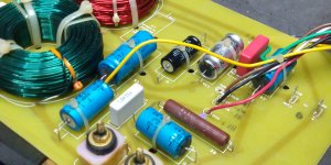
I got some pretty emblematic studio speakers some time ago but never hooked them up. So first they needed some love, cleaning and such. They are 3-way, massive speakers, Urei 813C. So before connecting them to the Bryston 4B NPB, I decided to check the crossovers, look for leaky caps and such. I certainly did not find any clear offender by inspection or individual component testing, so decided to fire them up. The sound was pretty midrangy. The manual did say that the speakers are really sensitive to installation position, that is something to have in mind.
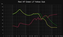
So decided to run a REW test, with the speakers connected, to see what type of curves they have. I am just tapping into the speaker terminals with a sweep. The results are attached. Some wacky curves going on. Tested the second one. Almost the exact same curves.
So questions have arisen: (bear in mind I am just starting to learn about speakers)
First, I suspect my measurement procedure is terribly flawed but,
If not that bad, then:
Are maybe those bumps trying to correct speakers?
Are those bumps normal if a crossover is measured like that?
Maybe crossover health is not that good?
Attached are pics and manuals.
Thank you all!
Attachments


I'm not entirely sure what your measurement is showing. Is that supposed to be an SPL plot? Because it sort-of looks like an impedance sweep. Which microphone are you using?
Chris
Chris
First, I suspect my measurement procedure is terribly flawed but,
If not that bad, then:
Please describe your measurement procedure .
🙂
I'm not entirely sure what your measurement is showing. Is that supposed to be an SPL plot? Because it sort-of looks like an impedance sweep. Which microphone are you using?
Chris
I did not change the units, sorry about that. It is just dB measured as a function of voltage at speaker outputs. Curves are the same in REW, no matter what units I choose. Just a different scale. No mic involved. I have successfully used this method to measure equalizers before, to incredible accuracy. Since the crossover is, in essence, a filter, such as equalizers are, I thought it could be a good idea.
Heres the REW file as well:
Rew file
Attachments

Last edited:
Please describe your measurement procedure .
🙂
Ok so REW sends an output sweep and gets it back as a voltage reading. Mic not needed if you want to measure an EQ. I have measured RIAA filters before and westrex cutting systems with the expected curves to +-1dB. What makes me think I could be flawed is that I am not measuring the speakers in the box and the fact that they are old. I think resonances, phase and a bunch of other things may work differently in this. Please correct me if wrong.
Cabinet and passive crossover designers freely flip wiring phase to drivers to suit other imperatives. If you're sharing the ground between stimulus and measuring, it could explain the unusual similarity between woof and mid.
You are correct about the drivers measuring differently in or out of the cabinet. But that difference would be pretty small compared to a ground problem.
Cheers
You are correct about the drivers measuring differently in or out of the cabinet. But that difference would be pretty small compared to a ground problem.
Cheers
Thanks, Rick.
So, do you think measuring only one driver connected at a single time would alleviate these issues? The manual warns about that being a potential issue with high-level signals but I am using 1 Volt so, do not think it is ever going to cause problems.
So, do you think measuring only one driver connected at a single time would alleviate these issues? The manual warns about that being a potential issue with high-level signals but I am using 1 Volt so, do not think it is ever going to cause problems.
The sub is not a sub it's a "helper" woofer and if you look at the schematic it plays with the 801c driver up close to the crossover to the compression driver. Look at the inductor value.
You have the drivers attached?? Just picking up the voltage at the terminals??
Rob🙂
You have the drivers attached?? Just picking up the voltage at the terminals??
Rob🙂
That's what he seems to do - at least according to his description. This doesn't make sense to me unless he tries to find the x-over transfer function in order to mimic it actively.
Driving a passive speaker with one or more drivers disconneced is dangerous for the amplifier driving it.
Try to measure the acoustic frequency response of the complete speaker if possible if you want to find out why (if at all) it sounds midrangey.
Regards
Charles
Driving a passive speaker with one or more drivers disconneced is dangerous for the amplifier driving it.
Try to measure the acoustic frequency response of the complete speaker if possible if you want to find out why (if at all) it sounds midrangey.
Regards
Charles
Last edited:
The sub is not a sub it's a "helper" woofer and if you look at the schematic it plays with the 801c driver up close to the crossover to the compression driver. Look at the inductor value.
You have the drivers attached?? Just picking up the voltage at the terminals??
Rob🙂
Yes, with drivers attached, measuring the voltage at terminals. Speakers in free air. Tiny signal of 1V.
My objective is to determine if the crossovers are working like they are supposed to do.
Yes, with drivers attached, measuring the voltage at terminals. Speakers in free air. Tiny signal of 1V.
My objective is to determine if the crossovers are working like they are supposed to do.
Why not just measure the speakers?? The manual has the plots at nominal and shows you what the changes are to expected depending on how you have the trim controls set. If the measurements are in agreement with this you should be good to go.
They will not be bass heavy The helper is a 2215/LE-15H so it's 40hz woofer with an underhung coil 1960 vintage design wise and limited x max compared to a modern driver. The woofer used in the coax driver is an E-145 which rolls of at about 80hz or so.
The range they do cover should be quite solid and fast. Remember designed for soffit mount so they may need some boundary reinforcement so up against a wall if needed.
Rob🙂
Firstly, I envy you---I have always wanted a pair of these. I think the UREI 813s are among the finest loudspeakers I have personally ever heard. Their stereo imaging is outstanding. They make it sound like you are at a live performance, which is why they were so popular in professional recording studios.I got some pretty emblematic studio speakers some time ago....... They are 3-way, massive speakers, Urei 813C. The sound was pretty midrangy.
Are maybe those bumps trying to correct speakers?
Are those bumps normal if a crossover is measured like that?
Maybe crossover health is not that good?
- Yes. I believe the bumps you are measuring are EXACTLY that--correcting for the speakers.
- Yes
- That's hard to say. I think I would measure each component by itself to verify performance. Let's face it---if these are original parts, they are 40 to 50 years old! The capacitors, of course, are the most likely to deteriorate with age; but I've seen resistors change also if they were heavily loaded. The inductors are not likely to have changed.
What he is measuring is called a V-plot. It is the transfer function of the crossover network with the actual driver loads connected to it. It is the first measurement that should be taken when evaluating any speaker system. It shows you how well or badly the crossovers are functioning. When dealing with older studio monitors and PA systems, they usually perform quite poorly.
Definitely don't take this measurement unless all crossover outputs are loaded. It may help to have the actual drivers connected, but normally an 8ohm resistor will work ok. In some cases, without the output loaded with the actual driver, the filter will ring.
This crossover has six inductors all oriented to maximize coupling between them. Four of them are very close to each other. I would start by fixing that and see how much the out of band filter responses improve. The HP filter on the tweeter section of this system is almost worthless. Major improves could be made in the system response.
If you go on to measure the acoustic outputs of each driver and its crossover section, you must cut some traces on the PCB to do this. Make sure that only the crossover components on the driver you are taking an acoustic measurement of are connected to the amplifier.
That's what it would be telling us, if a voltage source were in use. It appears that the speaker is being driven with the output of a soundcard, meaning there might be 600R in series with the whole shebang.
Using a power amplifier will allow the transcription of the crossover's slopes etc, but even then I'd suggest that's of limited use: crossovers are designed to work with specific drivers, and without knowing the acoustic response of such, the transfer function of the crossover is academic.
Chris
Using a power amplifier will allow the transcription of the crossover's slopes etc, but even then I'd suggest that's of limited use: crossovers are designed to work with specific drivers, and without knowing the acoustic response of such, the transfer function of the crossover is academic.
Chris
Chris,
It's not clear to me if there is or is not an amplifier between the soundcard and the crossover. Obviously there needs to be one or the measurements are junk.
Yes, properly designed crossovers are setup to work with the actual driver impedances connected to them. With resistors as loads on the crossover output, the V-plots would be meaningless.
Having V-plots of the actual system tells you a lot about the system behavior which is really important. In certain ways you can tell a junk design at that point without looking at any acoustic behavior. In my experience only around 25% of the professionals in this field understand how to take accurate acoustic measurements, having a nearly purely electrical measurement with no reflection sources to start with is very important.
Well the design of a UREI monitor is what it is. They may not be the bass-haviest monitors. But they have good transient response and this is definitely not due to a junk design crossover. 😉
Regards
Charles
Regards
Charles
Thanks for the answers, gentlemen.
The studio I got them from had a pretty good technical department, they used to maintain stuff in very good shape. That is what leads me to think they might be still ok, so testing before rushing to change all the caps came to mind first. From what I read, the 813C were made starting in 1984, the non C version, way before. These ones have the JBL drivers, so not that old of a design.
Here an extract from Mixonline.com
"In the mid-’70s, UREI founder Bill Putnam—unhappy with the sound of the Altec 604 monitors in his United Western Studios—worked with UREI’s Dean Austin and Dennis Fink on ways to improve the 604. They replaced Altec’s multicell horn with a wider dispersion design and added a 15-inch Eminence woofer to boost LF output. Ed Long applied his Time-Align™ crossover techniques to achieve time- coherent, true point-source performance.
Engineers and producers mixing on the system were so enthusiastic about its sound that UREI started producing the monitors as a commercial product, with the first UREI 813 debuting in 1977. Typically soffit-mounted, these large, double-15 monitors were ideal for the larger, higher-SPL control rooms of the time.
Two years later, Altec replaced its Alnico 604-8H with a ferrite model, requiring modifications to the 813 design, including a foam diffraction buffer, crossover mods and small Helmholtz resonators in the horn flare. This 1979 model was the 813A, followed by the 815A (a 604, plus two extra woofers) and the single-driver 811A, but the 813A was far more popular.
Financial and QC problems at Altec led UREI to find a new driver source, now mating PAS coaxial 15 to a JBL 2425 compression driver. The new 813B version debuted in 1983. Later that year, Putnam sold the business to Harman, with UREI becoming a division of JBL Professional; the 813C, a new model with all JBL drivers, launched in 1984. But in its various incarnations, the UREI 813 was the most successful large-format studio monitor ever made."
Chris,
It's not clear to me if there is or is not an amplifier between the soundcard and the crossover. Obviously there needs to be one or the measurements are junk.
Yes, properly designed crossovers are setup to work with the actual driver impedances connected to them. With resistors as loads on the crossover output, the V-plots would be meaningless.
Having V-plots of the actual system tells you a lot about the system behavior which is really important. In certain ways you can tell a junk design at that point without looking at any acoustic behavior. In my experience only around 25% of the professionals in this field understand how to take accurate acoustic measurements, having a nearly purely electrical measurement with no reflection sources to start with is very important.
I think we mostly agree - our differences are mostly semantics.
I don't mind much what the impedance curves of the drivers are - measuring the crossover in this way takes all that into account when the drivers are connected.
My point was more that taking the transfer function of the crossover tells only a part of the story: when you combine that with the raw acoustic transfer function of each driver, then we know how the speaker as a whole will work.
So, having a 3-way crossover where the mid output is 20dB down on the LF and HF might look very weird, but if the mid is a high-efficiency 6" unit mounted to a horn, combined with a 85dB@1w woofer and tweeter, then it's probably about right.
The LF bump in the measurements suggest to me that the crossover is being driven by a non-zero source impedance, and as you've noted, that would make the measurements taken so far essentially worthless.
Chris
Chris,
It's not clear to me if there is or is not an amplifier between the soundcard and the crossover. Obviously there needs to be one or the measurements are junk.
Having V-plots of the actual system tells you a lot about the system behavior which is really important. In certain ways you can tell a junk design at that point without looking at any acoustic behavior. In my experience only around 25% of the professionals in this field understand how to take accurate acoustic measurements, having a nearly purely electrical measurement with no reflection sources to start with is very important.
I am using the headphone amp in a TC Electronic Konnekt audio interface. The amp goes up to 3.5VRMS so 1V well within spec. Output impedance should be low enough as well. I could hook up the Bryston, if you guys think it would make a difference. When I tested the westrex 1700 cutting lathe EQs, an amp between the TC and the EQs did not improve things so that is why I did not use one here. Do crossovers react differently if fed by a larger voltage?
I have taken measurements of studios before with a calibrated mic, to create filters for room correction, with success. However, due to the speakers wanting to be soffit mounted, I expect some error. The plots in the manual do cover free space mount, which I suppose is just not soffit (they call in PI STERADIAN) with reduced bass response, tho. Anyways, they should still be quite flat to 100Hz in any case so, not reason to sound mid-heavy, if those plots are correct.
I do not think that if the crossovers were very out of spec, they would match so close in the plots as they do. But this is only a supposition. So more questions to the table.
Well the design of a UREI monitor is what it is. They may not be the bass-haviest monitors. But they have good transient response and this is definitely not due to a junk design crossover. 😉
I remember long ago when I worked with them in another studio room of the same facility. They sounded awesome. Bass was perfect. They were soffit mounted tho. I do not recall them sounding mid-heavy.
That's what it would be telling us, if a voltage source were in use. It appears that the speaker is being driven with the output of a soundcard, meaning there might be 600R in series with the whole shebang.
Using a power amplifier will allow the transcription of the crossover's slopes etc, but even then I'd suggest that's of limited use: crossovers are designed to work with specific drivers, and without knowing the acoustic response of such, the transfer function of the crossover is academic.
I tested all the caps by removing them from one of the boards and testing them with an LCR meter. Values are alright. However, Is it possible that even if values are ok, sound is not?
I think we mostly agree - our differences are mostly semantics.
I don't mind much what the impedance curves of the drivers are - measuring the crossover in this way takes all that into account when the drivers are connected.
My point was more that taking the transfer function of the crossover tells only a part of the story: when you combine that with the raw acoustic transfer function of each driver, then we know how the speaker as a whole will work.
So, having a 3-way crossover where the mid output is 20dB down on the LF and HF might look very weird, but if the mid is a high-efficiency 6" unit mounted to a horn, combined with a 85dB@1w woofer and tweeter, then it's probably about right.
The LF bump in the measurements suggest to me that the crossover is being driven by a non-zero source impedance, and as you've noted, that would make the measurements taken so far essentially worthless.
Chris
Alright, I am testing with the Bryston 4B NPB this weekend and sharing back.
- Home
- Loudspeakers
- Multi-Way
- Crossover REW Measurement for Urei 813C