Hello,
A simple 2-way crossover with simple drivers has turned into a nightmare. I am doing something wrong and don`t know what it is, would appreciate any input.
Pretty new to measurements but have played with Arta, Holm and recently - LSPCad. I prefer to use Holm for the moment. Mic is calibrated, mic preamp comes from a Behringer mixer, sound card ( Behringer ) calibrated as suggested by Holm and the rest, mic is mounted on a mic stand.
LR2 crossover, tried it at 2Khz, 2.2Khz and 2.5Khz. Using LSPCad I get a simulated response with a deep null as down as -50db which should indicate good phase tracking between the two. For the same crossover measurements at 1m, 2m, 2.75m never show a deeper null than 5-6db and it is wider than it should be - covering some one octave and a half.
Drivers are z-axis aligned - tweeter about 24mm behind the woofer, stepped baffle. Measured distance is approx. equal between each and the mic. Rise in impulse response with a sweep centered at 1Khz and another at 2Khz show rise to start at the same time 6.780ms for both drivers at the measurement distances, both feequencies.
Speakers are placed in the two corners of the room, drivers being some 70cm away of the back wall and about 50cm from side walls. I suspect that the room reflections introduce serious erros in the phase I measure as i do this in the room, not outside. No change is observed however at 2.75m and 1m respectively, dip remains the same.
I have attached the last crossover and the predicted response for the last crossover, still the measured reverse null dip remains at around -5db at crossover point.
Cap values are: 15uF for the batch on the left and 12.4uF for the one on the right.
A simple 2-way crossover with simple drivers has turned into a nightmare. I am doing something wrong and don`t know what it is, would appreciate any input.
Pretty new to measurements but have played with Arta, Holm and recently - LSPCad. I prefer to use Holm for the moment. Mic is calibrated, mic preamp comes from a Behringer mixer, sound card ( Behringer ) calibrated as suggested by Holm and the rest, mic is mounted on a mic stand.
LR2 crossover, tried it at 2Khz, 2.2Khz and 2.5Khz. Using LSPCad I get a simulated response with a deep null as down as -50db which should indicate good phase tracking between the two. For the same crossover measurements at 1m, 2m, 2.75m never show a deeper null than 5-6db and it is wider than it should be - covering some one octave and a half.
Drivers are z-axis aligned - tweeter about 24mm behind the woofer, stepped baffle. Measured distance is approx. equal between each and the mic. Rise in impulse response with a sweep centered at 1Khz and another at 2Khz show rise to start at the same time 6.780ms for both drivers at the measurement distances, both feequencies.
Speakers are placed in the two corners of the room, drivers being some 70cm away of the back wall and about 50cm from side walls. I suspect that the room reflections introduce serious erros in the phase I measure as i do this in the room, not outside. No change is observed however at 2.75m and 1m respectively, dip remains the same.
I have attached the last crossover and the predicted response for the last crossover, still the measured reverse null dip remains at around -5db at crossover point.
An externally hosted image should be here but it was not working when we last tested it.
An externally hosted image should be here but it was not working when we last tested it.
Cap values are: 15uF for the batch on the left and 12.4uF for the one on the right.
Last edited:
This is the first one I did for this speaker, before it - all were parallel. The thing is, no matter how well the simulated phase tracking is - when measured - it is never such. Usually in the range of 5-8db dip at xover freq, while the predicting software shows -40db for example. Tried asymmetrical crossovers, symmetrical LR2 - no deep dip at crossover frequency.
I was wondering, should I look elsewhere to obtain good phase tracking or the response I get is normal for inroom measurements with the defined setup. Unfortunately, speakers are very heavy to bring them out and measure there.
I was wondering, should I look elsewhere to obtain good phase tracking or the response I get is normal for inroom measurements with the defined setup. Unfortunately, speakers are very heavy to bring them out and measure there.
I thought this sort of thing looks better with suitable drivers:
http://www.diyaudio.com/forums/multi-way/206843-sreten-speakerman-go-series-xos-56.html#post3046046
Tony Gee at Humble Homemade Hifi archive might get your type of circuit working though. What drivers are you using? The acoustic centres might not be exactly where you are guessing either.
Haven't tried any of these circuits though, so it's all theory. 🙂
An externally hosted image should be here but it was not working when we last tested it.
An externally hosted image should be here but it was not working when we last tested it.
http://www.diyaudio.com/forums/multi-way/206843-sreten-speakerman-go-series-xos-56.html#post3046046
Tony Gee at Humble Homemade Hifi archive might get your type of circuit working though. What drivers are you using? The acoustic centres might not be exactly where you are guessing either.
Haven't tried any of these circuits though, so it's all theory. 🙂
Drivers are Scanspeak 18W4531G00 and Vifa XT25TG from the first batch.
But my question is mostly concerning the difference in the measured and estimated response and which one to trust. I have read that LSPCad does very accurate simulations that match closely the final result but in my case result is not very similar. As everything is calibrated, the only thing left I could think of is phase error caused by the nearby walls and corner placement but I would appreciate some comments on this and a possible cure.
I haven`t used Zobel on the woofer as its only 0.3mH and I found it unneccesary, tweeter has lots of ringing under 1.5Khz so went the other way, a series 1ohm ( to bring up minimum impedance to 4ohm ) plus 8.2_1ohm ( calculated for 4 ohms load ) L-pad seems to equalize it well and suppress the impedance peak at 500Hz. I would have gone for a 82uF_1mH_3.9ohm as I can still hear it ring but its Christmas and the component shops do not work 🙂
Last edited:
Never mind the measurements, why are you worried? Are they sounding bad?
Serial crossovers are terribly fussy things. You make the slightest change and they behave differently.
The null at crossover idea is OK in theory, but if you have the slightest level mismatch, it's going to degrade. -5dB isn't bad out of phase. That's about quarter power. Might just mean the tweeter or woofer level is slightly wrong. That could just be a question of a biggish DC resistance on a coil.
Looking at the Optimo PDF, you've moved quite a long way from the original filter design. The XT25 tweeter doesn't look all that different fron the scanspeak R2904-7000, but it's gotta have different efficiency and phase.
BTW, is your phase right? Tony Gee does it the other way round.
To get -40dB reverse null in 2kHz region requires exceptional control. Amplitude of woofer and tweeter must match to fractions of a dB. Phases must track to better than 2 degrees.
This is distances in millimeter range, and timing to microseconds.
Measurement must exclude reflections, and typically shorter measurement windows are used.
I've seen very few reverse null measurements of passively crossed speakers demonstrating -25dB. Best I've come across is about -35dB, from highly practiced builder with lots of measurement experience too.
-5dB reverse null is horrid.
Happy hunting
Hi Mario, I might not have read correctly but were you measuring BOTH speakers running in room for the above measurement?
If it is both then the interference between speakers will be overwhelming any difference you can see by reversing the tweeter polarity.
When I have done measurement comparisons to verify the accuracy of my sims I have done as follows.
Set up the speaker and mic, with the mic on axis with the tweeter (note this was with an MTM setup). at a distance of about 1M
Measure the tweeter response and lock time zero (in holm).
Measure the woofers response.
hook up the crossover and measure the system response.
export all of the measurements and import into speaker workshop.
simulate the crossover, and compare the simmed result with the actual measurement.
The important thing is that all measurements were taken with no change in the mic or speaker position.
I moved the speaker to the middle of the room and moved furniture out of the way to try and get the biggest distance possible between the speaker and any nearby surfaces. I believe that this may be an issue for you though.
Have you tried gating the measurement, the above graph looks like a raw response.
There was a thread before where people were measuring the left right canceling of there speakers by inverting the polarity of one. Finding the exact right spot to place the mic to get the best result was very difficult! movements of a few mm would result in quite different cancelation.
If you can't reposition your speakers I'd try taking a relative nearfield (gated) measurement at say 1/2 M on axis with the tweeter and see what that gives you.
Tony.
Will try to move the measured speaker in the middle of the room and measure it at 1m. I do zero-lock them ( based on tweeter initial measurement ) and then remeasure tweeter and woofer. Used gating too, no big difference. I had a big trouble reading the phase plots on Holm, but when imported to Speaker Workshop it looks much neater so will change speaker location and use this way to read the phase plots.
Problem was I couldn`t see the measured phase tracking very well on Holm so was relying on small value changes/measurements and simulations using LSPCad.
They sound average ( like a commercial speaker with some exagerated treble ) due to the 12db slope on the XT25TG even with the level of the tweeter padded down to some 2db under that of the woofer but I would rather replace it sometime in the future than to go steeper now. See no reason to use 30 euro components on 35 euro tweeter instead of buying a Peerless HDS or just a FE108EZ to run it as an OB tweeter from some 1Khz above. 🙂
Last edited:
Hi Mario, Note that the phase of the tweeter and the woofer will not necessarily track each other well on raw measurements of the individual drivers. What you do with the electrical filters (bearing in mind that the final acoustic slope is what matters) will determine how good the phase tracking through the crossover actually is. I used 2nd order electrical on my woofers and 3rd order electrical on my tweeters (with some playing around with cap and coil values in each) to bring the phase tracking to something reasonable. Note that these drivers are very close to time aligned, yet the phase tracking of the raw drivers is more than 90 deg out.
1st image shows the raw measurements of the individual drivers. 2nd image is simulation of actual crossover, it's not hard to see the difference in the phase tracking compared to the raw. 3rd image is a comparison of simulated vs actual (I had to grab this from the forum as I have lost those measurements 🙁.. note that the final measurement was actually done on a different day in a different location to the measurements used for the sim, but even so the correlation is pretty good. (on the third image, blue is the sim, black and green are the measurements of the left and right speakers, differences between the two quite possibly being due to slight positioning differences when swapping in the cabinets for the measurements note also the phase on this one seemed a bit sus, but it was a quick and dirty measurement).
Note also that I have noticed some weirdness at times with speaker workshop when simulating crossovers. Usually with the higher frequencies, sometimes being bumped up to spl's higher than the original measurements. It doesn't always do it, but it is good to superimpose the original raw measurements over the simmed result to make sure nothing funny is going on (adjusting for any padding if it is present).
Usually I sim the high and low pass networks separately, and then combine the two. If I notice any deviation in the high pass I adjust the levels down so the top end matches the original raw measurement before combining. Sometimes it seems to get a 2-3db boost.
Tony.
Attachments
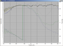
Ok, here`s an update. Managed to move the speaker in the middle of the room, approx. 1.6m away of side walls and 1.8m away of rear wall. Mic placed at 1m on tweeter axis. Used Holm, tweeter was used to detect zero-lock. Slopes are almost prefect LR2 centered at 2.2Khz, achieved with both 2nd order electrical on woofer and tweeter. Imported the measured response to Speaker workshop and phase was better to read there. Pics of how I left things today are attached, still phase tracking doesnt seem to look good but run out of time today, smoothing is 1/6oct, largest peak used.
Tweeter:
Woofer:
Tweeter:
An externally hosted image should be here but it was not working when we last tested it.
Woofer:
An externally hosted image should be here but it was not working when we last tested it.
Hi Mario, Could you export a gated response from holm for each driver and overlay them in speaker workshop with different colours for phase so that the two phase curves can be easily compared?
The phase will show fluctuations wherever there are FR fluctuations, so not doing a gated measurement will show the room effects in the phase response as well 🙂
Other that that your phase looks very flat so you must be doing something right! 🙂
edit: Actually if you could export impulse responses of the two drivers as wav files and zip them up and attach that would be helpful! 🙂
Tony.
Last edited:
Those from yesterday were gated 🙂 Have redone them today and merged the two charts. BTW - when I did smooth to 1/2oct in SW I notice the woofer phase to be some 20-25 degree away of the tweeter, will play until the NY party to see if I can get it any closer. Graphs are with normal tweeter polarity. Zipped impulse attached.
Black line: Woofer frequency response
Green line: Tweeter frequency response
Red: Tweeter phase
Blue: Woofer phase
Smoothing: 1/6oct
Black line: Woofer frequency response
Green line: Tweeter frequency response
Red: Tweeter phase
Blue: Woofer phase
Smoothing: 1/6oct
An externally hosted image should be here but it was not working when we last tested it.
Attachments
I downloaded above measurements and imported to Cool Edit. Ouch. Relative levels appear way off. Signal to noise ratio is very poor:

At 2kHz region should be possible to get clean windowed response. With appropriate windowing, no smoothing is required, and in any case should not be used for alignment purposes.
Keep working on measuring technique until results are consistent and repeatable.
Regards,
Andrew
At 2kHz region should be possible to get clean windowed response. With appropriate windowing, no smoothing is required, and in any case should not be used for alignment purposes.
Keep working on measuring technique until results are consistent and repeatable.
Regards,
Andrew
Yes I agree with Barleywater there is something very amiss with your measurements 🙂 I loaded into holm and the impulse response is all over the place. Definitely something not right there.
Have you done any loopback measurements to check that you are getting sensible results from your sound card?
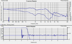
Just for comparison the first pic is your woofer measurement as it is showing for me in holm, and the second is my woofer measurement. The thing to look at is the impulse response. You need something clean like in mine to be able to get good results.
Note that on my measurement the impulse before the rise is completely flat whereas yours is showing considerable noise. After the impulse mine dies down, and it is easy to spot the point where the first reflection occurs.
Overall levels (between your measurements and mine) are very similar though, which makes me wonder if you have a problem with your soundcard setup. Perhaps it is monitoring the recorded signal (ie sending the recorded signal back out to the speakers) This really stuffs up measurements! My audigy has an option of record without monitoring which needs to be selected.
Start by doing a loopback measurement, and seeing if it is ok (it should give you a ruler flat response curve). Stop ALL programs that might try and use your sound card. If you have two sound cards, make the one your are not using for the measurements the default windows one and reboot before doing measurements. This made a huge difference for me.
edit: I just added a comparison image of the two impulse responses, zoomed right out. Note I just looked at the tweeter measurement and it looks quite a bit better than the woofer, but still noisy and something is not right.
Tony.
Have you done any loopback measurements to check that you are getting sensible results from your sound card?
Just for comparison the first pic is your woofer measurement as it is showing for me in holm, and the second is my woofer measurement. The thing to look at is the impulse response. You need something clean like in mine to be able to get good results.
Note that on my measurement the impulse before the rise is completely flat whereas yours is showing considerable noise. After the impulse mine dies down, and it is easy to spot the point where the first reflection occurs.
Overall levels (between your measurements and mine) are very similar though, which makes me wonder if you have a problem with your soundcard setup. Perhaps it is monitoring the recorded signal (ie sending the recorded signal back out to the speakers) This really stuffs up measurements! My audigy has an option of record without monitoring which needs to be selected.
Start by doing a loopback measurement, and seeing if it is ok (it should give you a ruler flat response curve). Stop ALL programs that might try and use your sound card. If you have two sound cards, make the one your are not using for the measurements the default windows one and reboot before doing measurements. This made a huge difference for me.
edit: I just added a comparison image of the two impulse responses, zoomed right out. Note I just looked at the tweeter measurement and it looks quite a bit better than the woofer, but still noisy and something is not right.
Tony.
Attachments

Last edited:
Hello and happy new year to all!
After I read your post, I double checked that I have the sound card calibration, it was checked. However, when I did a loopback measure, response was ragged as speakers inroom measurement. Unfortunately, it appears to be a Holm problem and I fear the inconsistency and weirdness of measurements comes from it. Anytime I restart Holm, calibration is lost, even if applied in the calibration panel.
When I did try to recalibrate, it does it and during the information analysis crashes. The only way around I found was to let it crash and then go to the measurements where it has DAC-ADC loopback on the blue panel, recheck that it is calibrated and then go ahead. Picture looks normal now with smooth response and more realistic phase plot. I use the 64 bit version on Win 7 64, not sure if this would be the problem.
Last edited:
I use the 64 bit version on windows7 as well. I have had problems with corruption, and have had to delete all of the files under the holm directory (I think they are xml files from memory). I'm on my XP laptop at the moment so can't check, but I think that they are somewhere under c:\users\username if you do a search on holm under that directory you should find them.
I routinely do a loop back measurement to make sure everything is working as it should. I get similar issues with my audigy, but I don't think the problem is with holm. A system reboot is the only thing that fixes it. I think it is a driver issue, and may be triggered by other software using the sound card. I actually go to the tray area and close every running program. Have a read of this post ---> http://www.diyaudio.com/forums/mult...d-farfield-does-look-right-2.html#post2446270 it was very helpful for me in getting to a state where I could get reliable measurements on windows 7 🙂
Tony.
edit: and Happy New Year! 😀
Last edited:
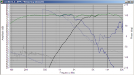
perhaps i mis read your graphs but
in the green trace there is a sharp null of 20db at 2.2khz. Is that measured or sim response?
in the green trace there is a sharp null of 20db at 2.2khz. Is that measured or sim response?
Hello and happy new year to all!
After I read your post, I double checked that I have the sound card calibration, it was checked. However, when I did a loopback measure, response was ragged as speakers inroom measurement. Unfortunately, it appears to be a Holm problem and I fear the inconsistency and weirdness of measurements comes from it. Anytime I restart Holm, calibration is lost, even if applied in the calibration panel.
When I did try to recalibrate, it does it and during the information analysis crashes. The only way around I found was to let it crash and then go to the measurements where it has DAC-ADC loopback on the blue panel, recheck that it is calibrated and then go ahead. Picture looks normal now with smooth response and more realistic phase plot. I use the 64 bit version on Win 7 64, not sure if this would be the problem.
Problem may be mixer settings for windows and/or sound card. If output is fed back onto input, extreme comb filtering effects are seen.
After the issue with the weird response was fixed yesterday evening, I played today and am almost done with the final version. Will increase the inductor a bit to 1.35mH tomorrow as today with 1.12mH I see the revelator still having a small bump at around 1.5Khz, the higher value should also push the phase of the woofer gently lower to match even closer.
Thanks for the Win 7 suggestion, will look for those folders as its quite annoying.
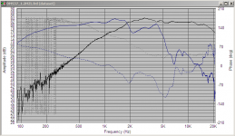
Now they`re crossed at 2.5Khz LR2, will try them tomorrow a bit lower at 2.2Khz or around. Thats how it looks with normal polarity, tweeter`s first order electrical and a very light L-pad to thame the ringing of the XT25, second on woofer, sensitivity around 87db at 4ohms if I can trust my measurement setup again 🙂
Thanks for the Win 7 suggestion, will look for those folders as its quite annoying.
Now they`re crossed at 2.5Khz LR2, will try them tomorrow a bit lower at 2.2Khz or around. Thats how it looks with normal polarity, tweeter`s first order electrical and a very light L-pad to thame the ringing of the XT25, second on woofer, sensitivity around 87db at 4ohms if I can trust my measurement setup again 🙂
Attachments
Last edited:
- Status
- Not open for further replies.
- Home
- Loudspeakers
- Multi-Way
- Crossover problem