Hello, dear friends!
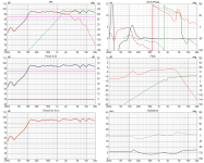
I'm designing a crossover for an active speaker on a tda7294 chip. The frequency response and impedance curve completely suit me. However, I don't have enough knowledge to evaluate the phase. Please check it. Do I need to make any adjustments to the diagram?
And a few more questions:
1) Will a polypropylene capacitor of type X2 (snubber type) have advantages over a conventional mylar capacitor in position C4?
2) How much worse would it be to use 2 electrolytic capacitors, anode to anode, in position C3 compared to Mylar?
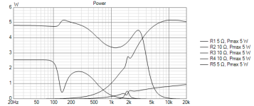
3) I can't figure out the resistor power dissipation graph in VituixCAD. With the "flat" option I need 5W. When estimating "m-noise" no more than 2W. What to choose?
Thank you very much!
I'm designing a crossover for an active speaker on a tda7294 chip. The frequency response and impedance curve completely suit me. However, I don't have enough knowledge to evaluate the phase. Please check it. Do I need to make any adjustments to the diagram?
And a few more questions:
1) Will a polypropylene capacitor of type X2 (snubber type) have advantages over a conventional mylar capacitor in position C4?
2) How much worse would it be to use 2 electrolytic capacitors, anode to anode, in position C3 compared to Mylar?
3) I can't figure out the resistor power dissipation graph in VituixCAD. With the "flat" option I need 5W. When estimating "m-noise" no more than 2W. What to choose?
Thank you very much!
Attachments


Thanks, this is the answer I was hoping to hear! )You should be OK so far.
Just for my information: what does the peak on the left side of the graph in the 150Hz area mean in practice?
The abrupt phase change goes with the sharp response rolloff. This is brought on by the midrange resonance impedance peak interacting with the crossover. Leave it there if you want, or if you want to change it take a look at the filter panel to see the effect of the crossover.
I apologize for the intrusiveness)The abrupt phase change goes with the sharp response rolloff.
I meant how would the sound in the 150Hz region change due to this peak in the phase graph? Will it become duller, fuzzier, or increase distortion? Or smth else?