There is something i find rather confusing, and that the delay x-over orders create. I always hear that using a 1st order will result in no phase change. However 4th order will end up with a 360 degree phase change. 3rd is 270 degree change and 2nd order 180 degrees. This leads me to believe that first order actually has a 90 degree phase change but because it's one low-pass and one high pass, they cancel each others time differences and therefore is phase coherent. This is probably true for a 2 way, but what about a 3 way were the midrange is using 1st order on both the high- and low-pass side? Also, does that mean that if using the same order of low- and high-pass the lead and delay will cancel eachother? And is this delay just phase related or time delayed as well? Because if so, as long as you have the crossover point low enough, the difference in orders between low and high pass can make the drivers time coherent even when the acoustic centres have different distances to the ear.
Don't know if I'm talking rubbish, but if you know, or know about any good source material I'd appreciate it
Don't know if I'm talking rubbish, but if you know, or know about any good source material I'd appreciate it
Vance Dickason Loudspeaker Design Cookbook is a good place to start.
9781882580330: Loudspeaker Design Cookbook - AbeBooks - Dickason, Vance: 1882580338
9781882580330: Loudspeaker Design Cookbook - AbeBooks - Dickason, Vance: 1882580338
https://www.passlabs.com/technical_article/phase-coherent-crossover-networks/
I just now found this; I haven't read it yet but it looks like it shows exactly what you have mentioned about phase.
I just now found this; I haven't read it yet but it looks like it shows exactly what you have mentioned about phase.
Sorry I don't have good source material to point to, but i do have the ability to measure xover typologies, from a processor with the outputs summed together.
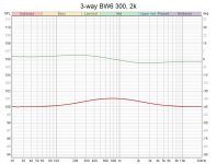
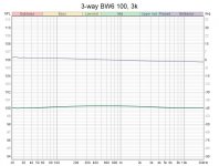
Below are 3-ways where all xovers are first order BW6.
As you can see, phase stays pretty dang flat. There are no delays involved.
The only thing is, the closer the two xover frequencies are together, the more they make a slight bump in the mid range response, and mess with phase a little.
As seen below...
This plot has xover at 300Hz and 2kHz

Where this one, with xover spread wider, is 100Hz and 3k

Below are 3-ways where all xovers are first order BW6.
As you can see, phase stays pretty dang flat. There are no delays involved.
The only thing is, the closer the two xover frequencies are together, the more they make a slight bump in the mid range response, and mess with phase a little.
As seen below...
This plot has xover at 300Hz and 2kHz

Where this one, with xover spread wider, is 100Hz and 3k

Group Delay is a topic that most people either are not aware of, or simply ignore.There is something i find rather confusing, and that the delay x-over orders create.
The effect of the (relative) phase angle is well understood and most people try to get good phase alignment, at least "on axis". You might have heard about "aligning the acoustic centers". Many people think that this means tilting the baffle back, or stepping back the location of the drivers on the baffle to physically align the drivers at the voice coil or some other physical location on the driver. OK, points for effort... it's not bad per se.
On the other hand it seems that the LARGE majority of people completely ignore the group delay profile (the frequency dependent delay) of the crossover filter networks. It doesn't matter whether its a passive or active crossover, the filters will impart a delay that will change with frequency. Only linear phase FIR DSP filters do not display this trait.
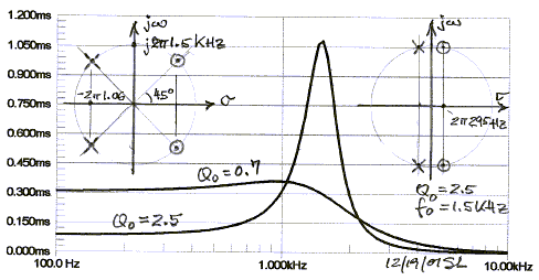
Here is an example, from SL's web site:

The above image shows the group delay of an LR4 versus some other filter (I assume its a 4th order filter) with a might higher Q. Let's focus on the LR4 GD response: it's the curve labeled "Q=0.7". Note the shape, and look at the left (vertical) axis. It's time in milliseconds. That's the amount of delay as a function of frequency for the summed output of highpass and lowpass LR4 filters. The amplitude (not shown) is relatively flat, however, you can see that high and low frequencies will emerge at different times, and around the crossover point there is a transition from more delayed low frequencies to very little delay at high frequencies. The magnitude of the delays depends on the crossover point, and is larger for lower crossover points. Basically the y-axis scales inversely with crossover frequency.
So in this particular example SL chose an LR4 @ 1.5kHz. Reading off of the plot, for frequencies below the crossover point the delay is around 0.3 msec and at high frequencies this falls back to essentially zero, but for example is down to about 0.10msec by 3kHz. It is the difference between these values that is important. For sound traveling at 345m/s, 0.3msec corresponds to a distance of about 0.1meter, which is about 4 inches! Likewise, 0.2msec (0.3msec minus 0.1msec) is about 2.6 inches.
What I feel most people do not understand is that that this group delay "timing" difference is exactly the same as MOVING THE DRIVER in space by the distance that corresponds to the delay. So all those well meaning people who align their acoustic centers BEFORE developing the crossover will totally screw up that alignment when the effect of the group delay of the crossover network is added of top of their physical offsets. And in this case, 4 inches is a big, big difference! This is why I find it rather dumb to physically align the drivers unless the offset is determined in concert with e.g. during the crossover design itself.
Also, it should be clear that the offset corresponding to the group delay and be much larger than most physical offsets arising from the various setbacks that arise from drivers with deeper cones, tweeters, etc.
As you increase the crossover order and the sharpness of the "knee", the group delay profile changes along with it. Steeper crossovers with a sharper knee will have more of the "peak" in the group delay plot that is shown above. Once this gets large enough, e.g. 1msec around 2kHz, some report this as an audible "ringing" type of hangover in the sound, and indeed there is actual ringing that can be measured in the time domain with an oscilloscope for a frequency around the crossover frequency in that case. This is even though the frequency response (steady-state FR) does not have a peak there.
The message I am trying to send is that DIYers should pay a little more attention to the group delay of their designs and take that into account just as they do the phase and amplitude responses. In my ACD design tools I calculate the system group delay so that the designer can take it into account. This should be a more standard feature in crossover design programs IMHO, because in some cases it can harm an otherwise good design.
Hi!
That was very interesting if i want to learn more who is SL and there is hes/hers website?
Maybee a stupid question but I’m a rookie.
That was very interesting if i want to learn more who is SL and there is hes/hers website?
Maybee a stupid question but I’m a rookie.
Siegfried LinkwitzThat was very interesting if i want to learn more who is SL and there is hes/hers website?
Linkwitz Lab - Loudspeaker Design
He is the Linkwitz part of the Linkwitz-Riley filter.
- Home
- Loudspeakers
- Multi-Way
- Crossover order delay