I am wondering how important it is to have a deep null at the crossover frequency when reversing polarity of a driver.
Lets assume we are dealing with a wide dispersion box design with a conventional 150mm to 180mm driver crossed over to a conventional 25mm dome at 2kHz to 3 kHz. In other words I am not talking about ribbons, horns, dipoles, or line arrays...
I have come up with filter circuits for the above situation which simulate as a flat response on-axis, and flat out to 30 degrees horizontally off axis... but when I simulate reversing polarity of the tweeter, I get a modest 6-8 db drop... not a deep null. I have other filter circuits which simulate a deep null of 25+ db.
Does the deep null result in a sonic benefit? Some designers seem to think so, while others do not emphasize this aspect.
Thoughts?
Jim
What xover order? Classic LR4 should have a deep and narrow null, as well as steeper even-order types; but LR2 will be a shallower trough.
Later,
Wolf
Later,
Wolf
From what I've observed, the deepness of the null seems to be most related to how close the phase is at the crossover freq. Two drivers whose phase overlaps ony at crossover point and diverge iether side may show a deep null but may not provide as good a result as two drivers whose phase tracks closely but not exactly over a wider range.
I look for a symetrical and even looking null.
The question become mute if talking about odd order crossovers 🙂
Tony.
I look for a symetrical and even looking null.
The question become mute if talking about odd order crossovers 🙂
Tony.
Take a look at the vertical off axis response. That is where the properly designed crossover reduces driver overlap and the resulting off axis response problems. I think you will likely find the deep null at some vertical off axis angle where the phase due to delay lines up. Boxsim free design software generates the off axis curves really nicely.
It is not important to have the null at the crossover frequency on-axis. However it is important that you know where it appears and what is happening on all axes.
To my experience, it's not so. The reason is that in LR4 the drivers are not really in phase but have a constant phase difference of 360°.Classic LR4 should have a deep and narrow null, as well as steeper even-order typestrough
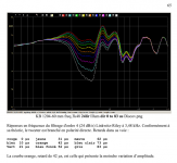
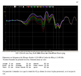
Here are two pictures of a LR4 configuration, the first one with direct (= non-inverted) connection and the second one with inverted connection. Various delays have been applied to the tweeter, with the idea that the deepest depression should give the best alignment. Drivers were ScanSpeak Discovery 100 mm and Illuminator 25 mm, crossover frequency 3.48 kHz, microphone distance 1204 mm. Determined by other ways, the best delay was determined as 42 µs (frequency response in orange color).
Attachments
Why not?
Unless you compensate the individual driver responses before the crossover is applied, you will not get the ideal LR4 response from each driver in the crossover region, and the sum will not look like the ideal LR4 sum or cancelation when one driver is reversed. If the crossover frequency is anywhere near the tweeter low frequency resonance and roll off, there is the added gain and phase response from that messing things up. That can be easily compensated for using a linkwitz transform to create half of the LR4 response using an active crossover. I'm not sure how to achieve that in a passive crossover. There is also the inductance of the woofer and breakup resonances that add gain and phase different than ideal to the woofer. If you look at the LR4 response using ideal drivers in the software model, you will see the sharp notch people are referring too. So an approximation to the LR4 response can be achieved in a passive crossover, it just takes a lot more parts than most people want to use.
To my experience, it's not so. The reason is that in LR4 the drivers are not really in phase but have a constant phase difference of 360°.
Here are two pictures of a LR4 configuration, the first one with direct (= non-inverted) connection and the second one with inverted connection. Various delays have been applied to the tweeter, with the idea that the deepest depression should give the best alignment. Drivers were ScanSpeak Discovery 100 mm and Illuminator 25 mm, crossover frequency 3.48 kHz, microphone distance 1204 mm. Determined by other ways, the best delay was determined as 42 µs (frequency response in orange color).
Unless you compensate the individual driver responses before the crossover is applied, you will not get the ideal LR4 response from each driver in the crossover region, and the sum will not look like the ideal LR4 sum or cancelation when one driver is reversed. If the crossover frequency is anywhere near the tweeter low frequency resonance and roll off, there is the added gain and phase response from that messing things up. That can be easily compensated for using a linkwitz transform to create half of the LR4 response using an active crossover. I'm not sure how to achieve that in a passive crossover. There is also the inductance of the woofer and breakup resonances that add gain and phase different than ideal to the woofer. If you look at the LR4 response using ideal drivers in the software model, you will see the sharp notch people are referring too. So an approximation to the LR4 response can be achieved in a passive crossover, it just takes a lot more parts than most people want to use.
The point of the null with conventional crossover alignment ( see S. Harsch crossover for a non-conventional alignment which does not meet this criteria) is to minimize destructive interference and improve off-axis response.
There are a couple of ways to get this:
1 - Use an asymmetrical crossover. In 2 way designs for instance, a 2nd order LP with 3rd order HP is typical.
2 - Tweak a zobel's values, both capacitance and R
3 - Tweak the crossover values, sometimes the R in a shunt component (going to ground) is ideal.
Best,
E
To my experience, it's not so. The reason is that in LR4 the drivers are not really in phase but have a constant phase difference of 360°.
Here are two pictures of a LR4 configuration, the first one with direct (= non-inverted) connection and the second one with inverted connection. Various delays have been applied to the tweeter, with the idea that the deepest depression should give the best alignment. Drivers were ScanSpeak Discovery 100 mm and Illuminator 25 mm, crossover frequency 3.48 kHz, microphone distance 1204 mm. Determined by other ways, the best delay was determined as 42 µs (frequency response in orange color).
The problem is that your drivers doesn't follows the LR4 responses enough in the measuring spot. If the drivers follow the LR4 slopes properly, then you can get a very deep reverse null if the drivers acoustical centers is in equal distance (or time aligned) to the mic position.
Last edited:
I would like to see people doing the same kind of experiences as mine.The problem is that your drivers doesn't follows the LR4 responses enough in the measuring spot. If the drivers follow the LR4 slopes properly, then you can get a very deep reverse null if the drivers acoustical centers is in equal distance (or time aligned) to the mic position.
The distance between the drivers axis was 120 mm. As already said, the distance from the front face of the loudspeaker to the microphone sensor was 1204 mm. The microphone axis was halfway between the drivers axis.
The crossover frequency being at 3.48 kHz, the tweeter main resonance at 500 Hz has a negligible effet on the response.
For use (listening music) I always include transforms on mediums and tweeters to avoid the effect of their main resonance on the responses of the filters. Just Linkwitz did in 1978.
LR2 reverse null is not shallower at any degree (why would be?), but wider than LR4.What xover order? Classic LR4 should have a deep and narrow null, as well as steeper even-order types; but LR2 will be a shallower trough.
Later,
Wolf
To the opening question, the answers will vary, some say the deep reverse null is important, others say it's not.
- Home
- Loudspeakers
- Multi-Way
- crossover null... how necessary?