Not Solen for tweeter and midrange !
Hi Dan,
why did you order the Solen caps ?
These are somewhat microphonic, thus you will not get the clearest sound possible from your tweeter and midrange.
Also, you do not need that large 400 volt size.
I recommend you send them back - and you do have a case for that given you were sent the incorrect Tolerance.
Falcon - if it is:
Falcon Acoustics | The Leading DIY Speaker Parts and Kit Supplier since 1972
have the 250 volt sized ClarityCap in the ESA range.
These are audibly much clearer than Solen !
and in the 250 volt size are not much more expensive.
Get those for tweeter and midrange, and as no 6uF in those
buy four of 3uF and connect as two Parallel pairs: 3 + 3 = 6uF.
If you don't want to use a Parallel pair, the 6.2uF is available in ClarityCap SA series from Hi-Fi Collective at:
amplifier valve kits, HIFI pre-amplifiers, speaker kits,AMP Parts, upgrade components
as also are the Mills MRA-5 resistors you will need.
Alcaps are Electrolytic and have significant Dielectric Absorption which causes a muddying of the sound.
I recommend you use polypropylene caps instead.
In Solen PA series 250 volt size not available from Falcon, but available from Canada and France via Mail-order,
use pairs of 36uF to sum to 72uF, or buy 33uF + 39uF = 72uF.
If you do not want to use parallel caps there, then buy 68uF for the output cap - the one nearest to the woofer,
and 75uF for the cap that connects between the two inductors.
This has been done by at least one Celestion Ditton 66 owner who reported good results.
The 250 volt size PA Solens are smaller than the 400 volt PB and will fit on the boards more easily.
If you don't want to buy from overseas, then there are the larger 400 volt size available in the UK,
and also in Janson Cross Cap which will work quite well in the bass filter section.
Last edited:
alan , what a dam shame i dident chek mail before i began soldering on one board so used half the load i got from falcon acoustics , i just finished fired up ,I have residual electrical noise which is isolated to speaker! it has lost its warm as a celestion i am really angry , i phoned falcon acoustics today , the solens did come in at _+5 the alcap 72 marked at 10_+
come in at 15_+ i rang was assured that the note explained , that these are hand picked from hundreds of caps , and my hand held meter was not hi spec enough its a DI LOG DL9206 and seems fine to me ??, as the ally foil caps are a different chemistry my reading will not be right ?? being a novice i said i will take his word for it , and went a head ,
regrettably
Alan i se your suggestions and am going to send the solens back for 250 volt sized ClarityCap in the ESA range. do you think the Alcaps caused the loss of base ,and electrical hum , i had a gut feeling these wouldent work out .? also the seas 737 did not drop straight in what a game , i have all tools etc being a carpenter as well as an idiot.
its late have to sleep
dan
Solen 70uF in 400 volt
Hi Dan,
if you are hoping to get the best sound from your speakers that you can within your budget,
it is more efficient to ask questions here before you buy,
even if it does take a few days to get a reply sometimes.
For the midrange caps, yes get the ClarityCap ESA 250 volt series,
and four resistors - read through this thread and find the resistance values that LucasAdamson used in his 44s, as he reported the sonic benefit,
and read my posts about why the resistors are needed, then you will get the warmth back !
All resistors will need to be at least 5 watt rated.
The wirewound resistors that Falcon sell are OK, but better can be bought from Hi-Fi Collective, or from overseas.
I see on the Falcon web-site there is now stock of 70uF Solens in 400 volt size
- look here:
Solen 70.00uF 400V DC FastCap Polypropylene Audio Capacitor from Falcon Acoustics, the leading supplier of diy hifi components.
If the physical dimensions will allow those to fit on your boards, then exchange the Alcaps for those,
and if you want to pay for selected Tolerances, ask Falcon to measure and send you 4 that are all on the + side of 70uF, as that will be close enough to 72uF.
When they arrive measure them with your meter and post the results here.
Alternately you can buy smaller physical sized for those from overseas, as I described in my last post.
To get the bass balance correct you will need 1.5 ohm in Series with the output cap, and 1 ohm in Series with the cap that is connected at the junction of the inductors.
About the hum you mention - first check that the cap's leads are securely soldered to the board's points
and that the other components soldered to each of those points have not become loose there.
As you are intending to install the SEAS tweeters you will need different capacitance values to what the Celestion tweeters required,
but you can use the old inductor if you connect a resistor in Parallel with the SEAS tweeter to match its Impedance to what is required for that inductor.
I have posted about this earlier in this Thread,
and in some places in the Celestion 66 midrange thread ... yes a lot of reading, but you will find useful information.
Look in the User Manual of your meter.
What accuracy specification is stated there for the Capacitance Ranges ?
- and what is the Test Frequency applied ?
Each capacitance range may have a differnt accuracy, and a different test frequency.
I have to go now, but do post what you prefer to do next
- before you buy anything that we have not discussed so that you can be confident of what may work better.
Last edited:
alan hi i just haven't had much time to get to grips with all that referencing but have am trying again
i have got to grips with all of this thread now , Lucas Adams project etc but arnt the 66 components different again in capacitor and inductor from 44s reading different references will confuse me further , thats not needed .
i am not that clued up how to calculate the new capacitor ,with resistor keeping old inductor ,with the seas737 ?? how do i do that ?
still going over thread i see lucas adams eventually used the seas 737 to but again had pr ordered caps and was experementing with the resistor s my 44 are pto point the older black front mk1 version
(As you are intending to install the SEAS tweeters you will need different capacitance values to what the Celestion tweeters required,
but you can use the old inductor if you connect a resistor in Parallel with the SEAS tweeter to match its Impedance to what is required for that inductor.
how do i do that going over thread for clues
i do have the specs for seas 737 tried to post dident happen to many caricatures so the page says i contacted admin support waiting to hear back
alan-1-b wrote
Strange you should say this 😕
I have used those Solen caps in as coupling caps in valve amps, SE and PP, in a valve phono stage and in 2-way speaker XO'ers and NEVER have I found these to be micrphonic.
In fact in a recent speaker build - a 2-way TMMMM design - I did for someone he reported back to me he thought his speakers sounded better than my original demo pair. I said the only difference between the two being the caps in the XO. In his I used the Solen 400V and in my demo pair I used Claritycap ESA 250V. Both sourced from Falcon Acoustics. You can make of this whatever you want. 🙄
why did you order the Solen caps ?
These are somewhat microphonic,...........
Strange you should say this 😕
I have used those Solen caps in as coupling caps in valve amps, SE and PP, in a valve phono stage and in 2-way speaker XO'ers and NEVER have I found these to be micrphonic.
In fact in a recent speaker build - a 2-way TMMMM design - I did for someone he reported back to me he thought his speakers sounded better than my original demo pair. I said the only difference between the two being the caps in the XO. In his I used the Solen 400V and in my demo pair I used Claritycap ESA 250V. Both sourced from Falcon Acoustics. You can make of this whatever you want. 🙄
ClarityCap , Solen , Ansar Supersound , and some other brands of capacitors.
Hi Toppsy,
interesting indeed what you have reported, and thankyou for doing so !
It has commonly been reported from some time more than a few years ago that Solen polypropylene capacitors are somewhat microphonic.
However, it seems to me from reading numerous posts, both in this Forum and in several others,
that the degree of microphonics may vary from batch to batch, or perhaps from capacitor to capacitor within any batch,
thus one does not know in advance what one may receive, thus why I have not been recomending them.
A few years ago the initial design of ClarityCaps became available to diy users.
{Previously these caps were only sold to large batch buyers - that is Loudspeaker Manufacturers, etc ...}
The ClarityCaps are manufactured in two ways to substantially reduce microphonics.
I substituted some of the earlier model ClarityCap PX series for Solen in a pair of my own loudspeakers and heard significantly clearer sound.
The manufacturer of Solen and SCR and Axon and a few other brands is Chartreaux {spelling ?} a French company.
They are a large company, and can afford to upgrade their manufacturing equipment, thus perhaps they have done so since becoming aware of the competition from ClarityCap
... but I do not know what the case is currently with Solen Chartreaux manufacture, thus I am still not recomending them,
except for the bass filter of Celestion 44 and 66 where any microphonics will be significantly less audible,
unless the sample is very faulty, then almost certainly the user will hear it and can return the cap as a faulty part.
I am recommending them for the bass filter section only because they are lower priced than the other brands,
and if one is on a low budget the limited money is better allocated to the best quality caps for the midrange and tweeter filters' sections.
Perhaps you have been fortunate to have received low microphonics samples.
Some listeners will not like very low microphonics capacitors - particually listeners who primarily listen to modern digital recordings of mainstrean Pop , Rock , and Adult Easy Listening styles of music,
because those recordings are so much treated with electronic processing during their mixing and mastering stages so as to render them clear sounding when heard via mediocre and poor quality audio systems that they sound anemic or lifeless when listened to via better audio quality systems.
For the case of those recordings some degree of microphonics and other resonances in the buyer's sound system causes the recordings to sound less anemic and a bit more lifelike !
My intention in this thread is to advise about the best possible audio results that one can obtain {within whatever specified budget} with worthwhile vintage loudspeakers.
I doubt that most listeners who prefer mediocre sound read these threads,
and if any do they probably do not continue with any of my recommendations.
If a capacitor is not physically vibrated in its location in any piece of equipment, whatever microphonics it has will not be as audible as when it is substantially vibrated,
thus perhaps your amplifiers are positioned so as to not be strongly affected by the sound from your speakers.
However, if the audio signal through a microphonic capacitor contains a significant amount of the frequency bandwidth that the capacitor is resonant in, then the capacitor will resonate internally.
--- --- --- --- ---
ANSAR and SUPERSOUND branded capacitors:
I posted earlier in this thread -{or perhaps in another thread - I have forgotten where}- that Ansar Supersound capacitors are made by the same manufacturer as Solen.
I was mistaken - they are not.
Ansar branded capacitors, whether with Supersound also on them or not, are made in the UK by Suppression Devices.
It seems from the information provided by Suppression Devices about their manufacturing process that these capacitors will not be substantially microphonic.
From the few reports I have been able to find to date by users of these caps it seems they allow good quality sound to pass without unpleasant additions to it.
I have not tried Ansar yet myself, however I may at some time.
They are not available in as many values as the new model ESA ClarityCaps,
and they are physically larger sized because they are 450 volt rated, versus the new model 250 volt ESA series -{which replaces the old 250 volt PX series}.
{There are also 630 volt rated ESA, but those are very large size, thus will not fit easily on old crossover boards.}
The available range of Ansar can be bought via mailorder from:
Cricklewood Electronics CCTV and Electronic Components
This company has been long established in the UK.
Most, but not all that range can be bought from Wilmslow Audio with the Supersound brand name printed on them.
One Celestion crossover restorer has reported good sound with these Supersound branded Ansars.
--- --- --- --- ---
Hi danodee,
I apologise, I am out of time now.
I will reply with details for you as soon as I have time available.
I have to find where I put the notes I made with the calculations for the parallel resistor to use with the SEAS 737 tweeter to enable it to work with the Celestion inductor.
Last edited:
L-Pad resistors for SEAS H737/19TFF1 tweeter
danodee,
I apologise for the delay in getting back here - I have had very little time available recently.
.
I have re-read Lucas' posts about integrating the SEAS H737/19TFF1 tweeter into his Celestion 44.
He had not fully decided on some matters about relative balance of outputs between the drivers as of his last post about such,
however he has given sufficient indication of what may be close to optimum.
.
First I refer you to this post:
http://www.diyaudio.com/forums/multi-way/93055-celestion-66-needs-mid-range-73.html
-
That should take you to Page 73 of the Celestion 66 midrange thread,
and if you look in Post #725 there you will see a Schematic diagram that can be enlarged - click your mouse over it.
-
Look at the tweeter filter there.
Shown there are the positions for the 2 resistors for the L-Pad.
These two, 15 ohms in Parallel and 1 ohm in Series, will cause as close as I can estimate to correct output from the tweeter to match the midrange of the 44
-{not for the 66, for which we found later requires less or no resistive attenuation}.
I cannot guarantee that you will prefer this option, but it is the one I advise you to start with,
unless you want higher output from tweeter than from mids - do you ?
.
Note, the capacitors there are for the old Celestion tweeter and not for the SEAS.
For the SEAS H737 the capacitors to use with the existing Celestion 0.14mH inductor are 3.6uF in the input position -{where the old 4uF cap is shown}-
and either 11uF or 12uF for the output position -{where the old 6uF cap is shown}.
The actual optimum value will likely be somewhere in between 11uF and 12uF,
and to decide exactly where one would have to measure the actual samples of tweeters being used, because there will be some small differences between tweeter samples,
BUT either 11uF or 12uF will get you close enough, thus buy whichever the seller of the 3.6uF cap has.
To get a 3.6uF cap of good audio quality in small physical size you will have to buy via Mailorder from SoniCap in the USA,
and they also sell good quality resistors - use the Mills MRA5 5 watt for the L-pad, and also for the other resistors shown in the Schematic in the midrange and bass circuits.
If you cannot buy from USA then to get 3.6uF in the UK you will have to buy the physically larger Jantzen, Z-cap from Audio-Components.
.
Note, Lucas used 3.9uF as the input cap and 10uF for the output cap.
This will work, BUT it will not produce a flat response output from the tweeter.
With 3.9uF and 10uF there will be a small peak in the output at a little higher in frequency than 5kHz.
.
In the Schematic is 82 ohms at the output in Parallel with the midrange driver.
You will not need this for the Celestion 44, and probably no resistor will be needed there.
The 1.8 ohms in Series with the 24uF cap is needed, or you will have louder midrange than bass, but this can be reduced to 1.5 ohms or less if you do want more midrange output.
The capacitor at the output in Parallel with the mid-driver is not 4uF in the 44, but is 6.2uF,
however you will need the 2.7 ohm resistor there or you will get an excessively resonant colouration in the upper midrange.
.
In the bass circuit if you still have electrolytic caps installed you will not need any resistors,
but if you have installed the polypropylene caps there the use 1.5 ohms in Series with the Parallel output caps, and 1 ohm in Series with the middle of circuit cap,
or you will get excessive resonant colouration in the low midrange.
Polypropylene caps plus resistors there will give clearer sound than electrolytic caps.
.
If you have any questions about any of the above, or about that Schematic, ask them here before you buy anything.
I will try to reply soon.
an alternate - for maximum output , plus a Correction
I last posted in a hurry as time was running out, and thus I did not proof-read.
Now I see an error in the second from final paragraph which may cause confusion,
so here is that paragraph again, and with the error corrected:
In the bass circuit if you still have electrolytic caps installed you will not need any resistors,
but if you have installed the polypropylene caps there then connect 1.5 ohms in Series with the parallel output cap,
and 1 ohm in Series with the middle of circuit cap,
or you will get excessive resonant colouration in the low midrange.
Polypropylene caps plus resistors there will give clearer sound than electrolytic caps.
--- --- --- --- ---
The last post {no pun intended} is for restorers who want to keep as close as possible to the original Celestion sound,
but with the greater clarity possible when using modern design polypropylene capacitors.
An alternate is to modify in such way as to get as much output as possible from the drivers,
and that will give a tonal balance that is closer to what well designed modern loudspeakers have ,
though not identical, nor entirely losing the Celestion 44 sound.
To achieve that completely the 3 ferrite cored inductors will need to be replaced,
with as low as possible DC resistance Air Core inductors in the bass section,
{try for less than 0.7 ohm each, and less than 0.5 ohm is better, but these will be large physical size}
and with an Air Core inductor with DC resistance between 1 ohm <--> 1.5 ohm in the midrange section.
The 2 air-core inductors in the old crossover do not need replacing.
I will comment more about new inductors if anyone here is interested,
but for now the other changes to get as much output as possible from the drivers are:
(a) - install Polypropylene capacitors in all the circuit locations.
(b) - connect 27 ohm, minimum 5 watt, resistor in Parallel with the SEAS H737 tweeter, and no Series resistor.
That is no L-Pad, but only a parallel resistor so that the 0.14mH inductor can be used.
(c) - in the midrange circuit do install the 2.7 ohm resistor in Series with the 6.2uF cap,
because that reduces resonance, not wanted output level,
{unless listener likes to hear resonant colouration in the upper midrange}.
In the midrange circuit do NOT install any resistor in Series with the 24uF cap.
(d) - in the bass circuit do install the 1 ohm and 1.5 ohm resistors where described above,
for same reason as (c) albeit for the lower midrange response.
(e) LISTEN using a wide range of the type of recordings that you want to get the best replay balance from.
It will not be possible to modify the speakers to suit all recordings, so be prepared to compromise.
You don't have to balance the speakers to suit only the most modern recordings.
You can balance the speakers to suit any vintage of recordings you prefer.
After listening:
- if the bass is too muddy or indistinct you will need to take out the old ferrite cored inductors.
- if the bass is OK in tone but is too low in level then:
are the mids too loud, or the treble too loud, or both too loud ?
If you have decided to keep the old ferrite inductors,
then for the one in the midrange circuit install a 0.47 or 0.51 ohm 5 watt wirewound resistor in Series with it.
This will further reduce resonant colouration in the midrange.
To reduce midrange output level, try 1 ohm in Series with the 24uF cap,
and if that is not sufficient drop of level, try 1.5 ohms.
If you happen to have 5 watt resistors in 1.2 ohm and 1.8 ohm , either can also be tried.
To reduce treble output level you will need to install 2 resistors in the L-Pad form, as described in my previous post, #247.
For small reduction of treble use 18 ohms for the Parallel resistor and either 0.5 or 0.68 ohm for the Series resistor.
I would try 0.68 ohm first, and that is available in Mills MRA-5, 5 watt, but if you can only easily obtain 0.5 ohm then try that.
If that does not reduce treble enough, then install the Parallel 15 ohm and Series 1 ohm as I previously described.
I have calculated the resistor values for the treble circuit for the total Impedance of resistors + SEAS tweeter to match what is required by the original 0.14mH inductor and the replacement capacitors I recommended to get as close as possible to a flat response from the tweeter as I can reasonably estimate without actually measuring the specific tweeter samples you will buy.
Last edited:
another Correction - about Jantzen capacitor type
I posted in #247 above that Jantzen Z-caps have 3.6uf in larger physical size than SoniCap.
That is not correct, my faulty memory !
The Jantzen capacitor range with the 3.6uF is their Cross Cap range.
Z-caps' ranges have less capacitance values, and the basic Z-cap range may not be audibly as good as the Cross Caps.
The other, higher priced, Z-cap ranges are physically much larger size, and have less capacitance values than Cross Cap range.
I would use SoniCaps for the midrange and treble,
and only the Cross Caps if I could not buy from the USA.
Last edited:
alan-1-b wrote
Oh, really😕 Where is your proof of this. I'm sure Solen would be most interested in your scientific research.
I do wonder whenever you sit down your voice becomes muffled. Because frankly you appear to talk out your **** as if you are some world authority on crossover caps. I do not make myself out to be an expert (in any field) but by virtue of the nature of the design of these caps and the materials they are made from they cannot be microphonic. Give us the proof of your statements please.
Oh! and one other thing. You write in an earlier posting
It has commonly been reported from some time more than a few years ago that Solen polypropylene capacitors are somewhat microphonic.
Oh, really😕 Where is your proof of this. I'm sure Solen would be most interested in your scientific research.
I do wonder whenever you sit down your voice becomes muffled. Because frankly you appear to talk out your **** as if you are some world authority on crossover caps. I do not make myself out to be an expert (in any field) but by virtue of the nature of the design of these caps and the materials they are made from they cannot be microphonic. Give us the proof of your statements please.
Oh! and one other thing. You write in an earlier posting
Chartreaux is a place in France NOT the name of the French Company. So do please get your facts right before you post.The manufacturer of Solen and SCR and Axon and a few other brands is Chartreaux {spelling ?} a French company.
There's no need of hate post unless you take this further.
I understand where Alan is coming from and he is only forming an opinion. From what I understand he can later debate that, somebody told him so from what I can guess or read between the lines...
The number two paragraph with the brands was later corrected a few posts after. I can't read anything new, unless there is some scientific data as you mention, to prove either way or about the phrase of the materials (Solen caps) "they are made from they cannot be microphonic" would be of a novel nature to me. Please explain so I can form an opinion. Do you mean a standard manufacturing process with standard materials and tolerances between different brands? Yes, I could believe that.
There were some closely related threads about microphonics about seven years ago over on the JBL/LansingHeritage site.
IIRC, part of the conclusion was that mounting techniques that reduce vibrations to the caps are a good thing ... and mounting the crossover externally is even better.
I think the Solens actually tested better than a few other film caps.
question arround a mystic microphonic problem in capacitor
IIRC, part of the conclusion was that mounting techniques that reduce vibrations to the caps are a good thing ... and mounting the crossover externally is even better.
I think the Solens actually tested better than a few other film caps.
question arround a mystic microphonic problem in capacitor
Last edited:
a Correction, and a Response to #250 on Page 25, and to others.
CORRECTION: "Chartreaux" is my incorrect spelling of Chateauroux, and as follows:
SCR stands for "Societe des Composants Record", which is a French Company located at Montierchaume,
which is very near to Chateauroux , if this map I have here is correct.
The company manufactures capacitors that are sold under "Solen" and "SCR" brands, and also branded with other names for some other companies.
My initial learning of these capacitors was result of them being refered to as "Chateauroux" by several users of them.
This includes a designer of loudspeakers I met years ago who said he preferred the sound of "Chateauroux capacitors" in his designs to another type we discussed then.
Also, "Chateauroux" was used in at least one reference to these capacitors in a feature article published in "Hi-Fi News" magazine during the 1980s.
Later I became aware that the capacitors being called "Chateauroux" were the from the same manufacturer as "Solen" capacitors.
--- --- --- --- ---
Toppsy,
I am beyond puzzled to almost astounded by your response to my postings,
as apart from the error above, I can not find anything I've written which seems to justify the nature of your response.
I thanked you for the information you posted in your initial response - #245 on Page 25 -
to my earlier post about microphonics in Solen capacitors,
because I thought the information you posted was useful to readers,
and I still do think that.
So far as I understand, this Forum is for members to share information and experience.
That is what I attempt to do.
I do not presume myself to be a "world authority on crossover caps".
I have posted in this thread matters about capacitors for crossovers that I have found in other Audio related Forums ,
in Blogs on enthusiasts' web-sites , in some Magazine articles , in some Manufacturers' information , etc ...
Anyone can do a web-search and find similar and some the same as I found.
Here is a recent updated report of a previous published by the manufacturer of ClarityCaps.
It includes about microphonics:
http://www.partsconnexion.com/t/claritycap/Reseach_Summary.pdf
-
The manufacurer of "Solen", etc ... will be aware of research done and reports published by ClarityCap, and in order to compete and keep their customer base they may have improved their manufacturing process since, but I do not know at this time.
What we can do in this Forum is discuss our findings.
That is what you presented in your initial post, and what I and others have done in many posts.
This is what at least some of us will continue to do as more capacitors are tried, etc ...
Regarding your other remark,
Ultimately it does not matter which orifice I am talking through, as long as the information is heard by whom it is directed to.
Of course, if my voice sounds muffled then either I am using poor quality capacitors or inductors, or I do not have the filter tuned well enough.
--- --- --- --- ---
Basically, how caps can be microphonic:
If the tension is not completely evenly mantained across the full width of the two foils whilst the capacitor is being wound,
then regardless of how tightly most of it may be wound,
and regardless of how much epoxy or similar that is applied to both ends of the final rolled component,
there will be inside the capacitor some areas of one foil that are of slightly lesser tension than some areas that are in the opposing foil.
That is, there will in effect be one stiffer charged plate in proximity to one more flexible oppositely charged plate.
A Condenser Microphone has a charged, edge suspended diaphragm vibrating beside an opposite polarity charged fixed plate.
When a vibration is applied to the moveable diaphragm, there is then an alternating difference in Voltage between the diaphragm and the fixed plate as result of the changing electrostatic field between the plates.
That alternating voltage becomes the audio signal.
Thus, even when such as inside a rolled capacitor where the specific roles of each plate are not defined as in a Microphone, so long as one plate is vibrating at a different amplitude to the other in any particular area there will be an alternating voltage generated by the changing electrostatic field there.
This voltage may be small in any single area, but there is a very large amount of area inside capacitors of the capacitance quantities used in crossovers,
thus when a lot of small vibrating areas are summed the final result is sufficient to be audible through the speaker driver connected to the capacitor.
--- --- --- --- ---
Hi Inductor,
I am not gifted with much ability for communicating concise but comprehensive explanations of some phenomena,
but the above about microphonics in rolled capacitors is an attempt.
-
Hi sba,
Thankyou for posting the Link to that test.
I have seen similar published in a technical magazine's article.
{I've forgotten the Title of the magazine, though I probably have the issue with the test somewhere amongst my collected multitude of print items !}
Also, I have seen either similar on another web-site, or perhaps it was that same one that you posted - I have forgotten.
I read so many things that I cannot remember where all the results that I do remember were originally published.
Last edited:
midrange cone driver in Ditton 44
Owners of Celestion 44 ,
I recommend you go to this page:
http://www.diyaudio.com/forums/multi-way/93055-celestion-66-needs-mid-range-91.html#post3164572
and read Posts #907 <--> 910.
This could benefit the woofers also, and likely the drivers in many vintage loudspeakers, including other Celestion models.
The above are on Page 91 of the Celestion 66 midrange thread, if the Link takes you to another page after more posts move that thread along.
Last edited:
hi alan how are you , many thanks for this 25th May 2012, 11:20 post its very clear and helpfull
visited today inspired me to get back on track with my 44 project . i always have one reference 44 not touched , i have been running the pair and need some tweaks on modified ,,
i will post new caps installed and audible feedback , complete and post response chart
but dont have original 44 chart to compare ,?? what always confuses me here is ,(i have 44s but get referenced to 66s so a 66 frq response diagram will be different ? i dont know
all best
dan
Celestion 44 charts
'ullo dan ,
for original information about Celestion 44 , including parts' lists and schematics ,
go to Page 19 of this thread , and there to #188 by rwtomkins.
I previously referenced you to the hand drawn schematic of the 66 circuit so that you could see where the resistors are to be connected for use with modern polypropylene capacitors.
I do not know where there may be a plot of the frequency response of the 44 , but do not worry about that.
After you install the new capacitors and the resistors , listen to several recordings that you know well ,
and that you think should benefit from the upgrade of the crossover.
Post about those when you are finished and have listened for a while.
Good Day!
Well, what started off as a simple job to replace the binding posts in my blackie Celestion Ditton 44s, has turned into a cross-over rebuild project. After the speaker terminals were replaced, I plugged into my amp, and got nothing out of that channel. I have isolated it down to the crossover, I think, as I am measuring 2.7 ohms across the speaker terminals. Hopefully a driver didn't go, but I am doubtful, since I didn't get any sound out of the speaker after I changed the terminals. I've taken pictures and drawn a diagram. The cross-over is the older point to point board.
With New Years just around the corner, it will be a few days before my next post, but it will include pictures.
Happy New Year everyone!
Pictures
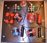
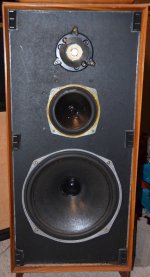
I love these speakers. They sound very sweet, at medium and low volumes. I suspect these are the 50 Watt versions.
The first crossover is my suspected bad unit. I suspect C2. The numbering is based on the designation from another crossover diagram on the Midrange Muddy thread. When I put the ohmmeter on it, it does not behave as a cap should. It also doesn't look too good, which is why I checked it first.
Happy New Year!
Attachments
-
 Celestion Ditton 44 bad cross-over 3739.jpg720.3 KB · Views: 353
 -
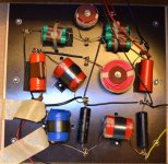 Celestion Ditton 44 Working cross-over 3742.jpg723.1 KB · Views: 315
 -
 Celestion Ditton 44 bad unit 3748.jpg412.8 KB · Views: 313
 -
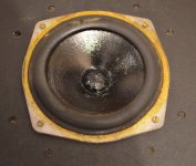
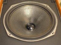 Celestion Ditton 44 Bad LF Driver 3730.jpg782.6 KB · Views: 292
 -
 Celestion Ditton 44 LF Driver 3740.jpg762.1 KB · Views: 301
 -
 Celestion Ditton 44 bad MF Driver 3731.jpg642.3 KB · Views: 96
 -
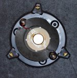 Celestion Ditton 44 bad HF Driver 3749.jpg822 KB · Views: 113
LOL, too funny! I was just re-reading this thread from the start, and I encountered post 17 on page 2. I totally didn't consider the serial number plaque where the speaker terminals are, and immediately after reading that post I thought, no, it couldn't be. Sure enough, with no cables and the crossover removed from the cabinet, it buzzes continuity.
Well, obviously, I need to replace the caps in the crossover, so I will continue on this project.
Cheers!
Well, obviously, I need to replace the caps in the crossover, so I will continue on this project.
Cheers!
Last edited:
Hi TechnoDweeb ,
then it is good that you read from the start of this thread ,
and thus how new owners can find unexpected things when restoring vintage loudspeakers !
Your photos here are useful as they show another version of what can be found inside 44s.
I see some-one installed electrolytic caps in the tweeter filter section - ugh !
The input caps' combination of the midrange filter is visibly different for each of your samples , but may have caps that sum to the same total ,
but if not then check the original schematic posted in this thread.
Really I do not know whether better to use 24uF or 30uF there ,
and it may be better to use whichever was for which of the 2 different versions of the midrange driver that Lucas Adamson posted about in this thread ,
depending on which version you have ...
or use the in-between common value of 27uF , or the 25uF ClarityCap -{see below}.
As you are in Canada there is good choice of capacitors available via Mail-order , such as from:
Parts ConneXion - The authority on hi-fi DIY parts and components
where you can buy AXON True Cap in 36uF to use in parallel pairs to sum to 72uF ,
and the Mills MRA-5 compensating resistors I recommended in this thread.
I recommend you do not use the AXON caps for the midrange and treble ,
but use ClarityCap instead , and if the type Parts Connexion sell are above your price range , then
Madisound Speaker Components: distributor of loudspeaker drivers and parts for speaker builders.
sell the lower priced PX series of ClarityCap which are good enough ,
or find the Sonicap web-site , USA , and buy their own brand via Mail-order ,
plus the Mills MRA-5 resistors.
About your final post in the Celestion 66 midrange thread ,
yes , felt around the tweeter will sweeten up the sound , as it will for the 44.
I will be posting more about felt treatment for front baffle panel in the 66 thread when I have sufficient time available.
Last edited:
- Status
- Not open for further replies.
- Home
- Loudspeakers
- Multi-Way
- Crossover nightmare!!!!!!!