Apologies - a delay of a few days responding to the most recent post...
To answer these Qs: On the head unit, the signal output ground side is grounded to chassis. The signal side is 0v to the chassis ground.
It is an old 1990s Volvo car amp - 4 x 20W (#3533004 or HA-4120) - works ok and would be fine for the tweeters. It is very simple - not much in there - a pair of TDA1552Q which are 2 x 22W BTL. There is a transformer, but the supply voltage to the amp chips is not increased from the supply amount of 14.4v.
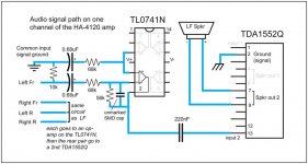
Attached is a circuit diagram of one of the audio signal paths in this amp - so it can be assessed regarding changing caps for high-pass - I tried to make this image using an online circuit creator, but this screwed up so I just drew it offline. It is one channel, but all four are all the same obviously. Though - I do 'get' that the best option would be a pair of active crossovers...
With the active crossovers - how about these: It's a PCB with a design based on NE5532 op-amps. This could be a good idiotproof option because there'd be a circuit design already laid out. It takes single-rail power.
https://www.ebay.co.uk/itm/12453469...i416eOSjueDR2u7i0YCbv1k+8U|tkp:Bk9SR6aA4bDIYQ
This seller also does a 2-channel, 2-way active crossover, but it wants +/- power. I'm still trying to find suitable examples of power-supply circuits for powering op-amps off a single-voltage source... (admittedly this active crossover would not take much power and it's advertised as capable of running off 5v-0-5v).
This is something I'd like to know more about - it is relevant here but it's obviously also its own whole topic... But are you talking about using a small step-up/boost convertor like a XL6009 type unit from ebay to (for instance) double the voltage, then split that with a virtual ground, or are you talking about a circuit which does all that from the ground-up?
Thanks much appreciated.
You can measure the DC voltage on the negative signal line to see if it's 0v or something near 6v. The signal line should also be very near 0v but leakage through capacitors may let it float slightly
To answer these Qs: On the head unit, the signal output ground side is grounded to chassis. The signal side is 0v to the chassis ground.
What is the 20w/ch amp that you have.
It is an old 1990s Volvo car amp - 4 x 20W (#3533004 or HA-4120) - works ok and would be fine for the tweeters. It is very simple - not much in there - a pair of TDA1552Q which are 2 x 22W BTL. There is a transformer, but the supply voltage to the amp chips is not increased from the supply amount of 14.4v.
Attached is a circuit diagram of one of the audio signal paths in this amp - so it can be assessed regarding changing caps for high-pass - I tried to make this image using an online circuit creator, but this screwed up so I just drew it offline. It is one channel, but all four are all the same obviously. Though - I do 'get' that the best option would be a pair of active crossovers...
With the active crossovers - how about these: It's a PCB with a design based on NE5532 op-amps. This could be a good idiotproof option because there'd be a circuit design already laid out. It takes single-rail power.
https://www.ebay.co.uk/itm/12453469...i416eOSjueDR2u7i0YCbv1k+8U|tkp:Bk9SR6aA4bDIYQ
This seller also does a 2-channel, 2-way active crossover, but it wants +/- power. I'm still trying to find suitable examples of power-supply circuits for powering op-amps off a single-voltage source... (admittedly this active crossover would not take much power and it's advertised as capable of running off 5v-0-5v).
The split supply can be produced in several ways. You can buy small switching power supplies from ebay. It's not difficult to make your own. The most difficult part is sourcing a suitable core and that's not too difficult. A lot of people make the mistake of using an inductor core. They look the same but have very different properties.
This is something I'd like to know more about - it is relevant here but it's obviously also its own whole topic... But are you talking about using a small step-up/boost convertor like a XL6009 type unit from ebay to (for instance) double the voltage, then split that with a virtual ground, or are you talking about a circuit which does all that from the ground-up?
Thanks much appreciated.
Attachments
For that circuit, I think I'd simply insert a 3000pf cap in series with the positive signal input and work from there. I can't say whether that value will definitively give you what you want. You could go with a higher value if you don't need so much filtering. This should be for about 5000Hz. Someone should correct me if this is wrong.
Those crossovers should work well enough.
The supplies I'm referring to would be something like ebay auction:
314198295084
They will work for small preamp circuits. The larger supplies with toroidal transformers and heatsinks are not much more but mush have isolation for the secondary and must produce the ±15v that the preamp circuit would need.
