I measured the inductance of different inductors and found a rather high dependence on frequency in some cases. With my LCR bridge I can only measure @ 1kHz and 10 kHz but from my woofers response I can see that it extrapolates to lower frequencies as well. Especially one EI-cored foil indcutor stood out with a delta of 20% difference between 1 and 10kHz.
From what I have read: In case of cored inductors this has mostly to do with the frequency dependend magnetic susceptibility of the core material used. With air inductors some claim skin effect and or parasitic capacitance.
From the limited data I have gathered it seems the nominal inductance manufacturers print on their cored inductors are rather a ballpark figure as neither the frequency the measurement was taken at nor any non-linearities are usually specified. In practical terms this would mean that I have to change windings or the core gap to get the desired result especially with inductors that use a lot of core material.
Is this a known fact or am I totally wrong somehow?
Many thanks for your comments .
Ozo
From what I have read: In case of cored inductors this has mostly to do with the frequency dependend magnetic susceptibility of the core material used. With air inductors some claim skin effect and or parasitic capacitance.
From the limited data I have gathered it seems the nominal inductance manufacturers print on their cored inductors are rather a ballpark figure as neither the frequency the measurement was taken at nor any non-linearities are usually specified. In practical terms this would mean that I have to change windings or the core gap to get the desired result especially with inductors that use a lot of core material.
| nominal value /mH | Inductance @ 1kHz / mH | Inductance @ 10kHz / mH | Delta / % | |
| Air coil: Wire | 0,75 | 0,756 | 0,695 | 8 |
| Air coil: Foil | 0,47 | 0,47 | 0,455 | 3 |
| E-core (laminated ferrosilicon): Wire | 4,7 | 4,427 | 4,069 | 8 |
| EI-core (laminated ferrosilicon): Foil | 6,8 | 7,5 | 6,1 | 19 |
Is this a known fact or am I totally wrong somehow?
Many thanks for your comments .
Ozo
Last edited:

Traditionally, laminated cores start to fade past 300Hz due to eddy-currents pushing the flux out of the core. A gap swamps this effect but leads to a much larger product. The values you found are probably fine commercial compromises. Why would we care about a 7mH coil at 10kHz? (>400 Ohms) Even 7mH at 1kHz is 44 Ohms not 8 Ohms. You might want to sweep that one from 100Hz to 400Hz, where it would more likely be used.
Don't you mean "frequency dependent impedance"?
I broke down and bought a network analyzer several years ago, then I bought another one...fascinating the interplay of parasitic components...
It would also be interesting to see the inductance vs excitation level. An issue for signal transformers.
I broke down and bought a network analyzer several years ago, then I bought another one...fascinating the interplay of parasitic components...
It would also be interesting to see the inductance vs excitation level. An issue for signal transformers.
As jackinnj alerts, your measured inductance is likely quite dependant on excitation voltage, and it is plausible that your LCR bridge uses a different excitation voltage for 1kHz and 10kHz. You should be able to confirm the excitation voltage with a suitable meter that has flat response out to beyond 10kHz.
High permeability laminations have shown a constant permeability at low frequency out to a corner that is likely well below 1kHz - with permeability dropping at higher frequency - that particular effect of falling permeability is rapidly diluted with interleaved core laminations or even more so with a dedicated gap as PRR notes. References by Heck 1974 and Lee 1955 comment on that.
High permeability laminations have shown a constant permeability at low frequency out to a corner that is likely well below 1kHz - with permeability dropping at higher frequency - that particular effect of falling permeability is rapidly diluted with interleaved core laminations or even more so with a dedicated gap as PRR notes. References by Heck 1974 and Lee 1955 comment on that.
Does anyone understand why the inductance of the air core inductors also goes down with frequency? A parasitic shunt capacitance should cancel some of the inductive susceptance and make the effective inductance go up.
Lee 1955 is surely Ruben Lee, Electronic Transformers and Circuits, a sweet book and now a free download:References by Heck 1974 and Lee 1955
http://www.tubebooks.org/books/lee_1955_electronic_transformers_and_circuits.pdf 23MB PDF
Heck was not known to me. There is an eBook, not free:
Magnetic Materials and Their Applications, 1974, Carl Heck, eBook ISBN: 9781483103174
https://www.elsevier.com/books/magnetic-materials-and-their-applications/heck/978-0-408-70399-4
Google Books has a preview (seems extensive, 150 of >700 pages)--
https://www.google.com/books/editio...d_Their_Application/yvEkBQAAQBAJ?hl=en&gbpv=1
Sorry, I was a bit curt on the references:
Heck’s 1974 book ‘Magnetic Materials and their applications’ identifies an almost constant permeability below a critical frequency, where the critical frequency reduces for high permeability material and thicker sheet. I have the book, which makes it bit hard to then use as a reference 🙂
Lee’s 1955 book ‘Electronic transformers and circuits’ Figure 162 on page 217 shows a 0.014” GOSS example that is applicable to OPT lamination thickness and material and shows permeability falling rapidly above 1kHz, indicating the critical frequency is well below 1kHz.
Footnote calls this journal article which seems on-point.Figure 162 on page 217
The Variation of the Magnetic Properties of Ferromagnetic Laminae with Frequency
Author(s): C. Dannatt
Source: Volume 79, Issue 480, December 1936, p. 667 – 680
DOI: 10.1049/jiee-1.1936.0209 , Print ISSN 0099-2887, Online ISSN 2054-0612
https://digital-library.theiet.org/content/journals/10.1049/jiee-1.1936.0209
Buy article PDF $19.95 (plus tax if applicable)
Many thanks for all the valuable information @everybody. I made some additions to my LCR bridge so I could measure more frequencies. In the meantime the coils were slightly modified with more windings or a bigger gap to fit my needs.
Whilst measuring the self resonant frequencies I found most of the foil coils to behave odd. Despite having a higher Q the ringing subsided after 1-2 cycles whereas most coils made out of wire rang for many cycles.
The take away for me is to go no further than E-core, as too much high frequencies might bleed through and to buy only coils that can easily be modified in terms of windings.
.PNG")
Whilst measuring the self resonant frequencies I found most of the foil coils to behave odd. Despite having a higher Q the ringing subsided after 1-2 cycles whereas most coils made out of wire rang for many cycles.
The take away for me is to go no further than E-core, as too much high frequencies might bleed through and to buy only coils that can easily be modified in terms of windings.
On vacum tube output transformers a study showed at 20hz core induction was 80 % and at 20khz is was only 2%.
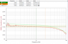
Here's a chart of inductance vs frequency for signal levels of -30, 0 and 13dBm (7.071mV, 223.6mV, 1.000V). Inductor is a Rockford Fosgate 3.2mH. The effect seems to be trivial at these low voltages, and may just be noise or uncertainty in the measurement,It would also be interesting to see the inductance vs excitation level. An issue for signal transformers.
Attachments
To decide which coil I wanted for my woofers, I had to get a ball park figure on distortion as well. So I performed a small test with amp, coil and power resistor (6 Ohms) in series and measured the distortion on the resistor. Amp output was constant at 5.6 V, 100 Hz and I varied the coils - all kinds of make and model. Not really scientific but enough information for me.
I was surprised to find some distortioneven on air inductors and how good the laminated E-cores were. I had no laminated I-core at hand but I guess they are at least as good as the E-core. The best air inductors were indeed made of foil, but the difference is very small. Yet in listening tests I do prefer the air foil inductors over wire by a not so small margin.
So for me it is laminated ferrosilicon E- or I-Core made of thick wire on the woofer low pass and air foil everywhere else.
Edit: I found the issue with the air-coils: I had some metal parts in close proximity
| THD/% | |
| no coil | 0,004 |
| Air (wire and foil) | |
| E-Core (laminated ferrosilicon) (wire and foil) | 0,03 |
| "small I-Core" (soft ferrite) | 0,38 |
| P-Core | 0,63 |
I was surprised to find some distortion
So for me it is laminated ferrosilicon E- or I-Core made of thick wire on the woofer low pass and air foil everywhere else.
Edit: I found the issue with the air-coils: I had some metal parts in close proximity
Last edited:
I have only one Litz installed in my crossovers atm. When I have refined my measurement methods to show a meaningful difference between foil and wire reliably I might test them as well. I would put the Litz somewhere between foil and wire soundwise. Although I do not understand why the foil sounds so detailed yet smooth compared to wire.
When I did the AB comparo, the crowd did not subjectively prefer the foil at all. I had Litz, foil, round wire, Pcores, and steel laminate. Steel laminate had the top spot for the 10 minutes. Pores and foil were the lowest and Litz/round in the middle.
In my own trials, I prefer the Litz on woofers, and round on tweeters. I core had an artificial quality and emphasis that got old for me. Litz on woofers had more detail than round and foil, and the round sounded "drier" by comparison, with the foil being less revealing.
In my own trials, I prefer the Litz on woofers, and round on tweeters. I core had an artificial quality and emphasis that got old for me. Litz on woofers had more detail than round and foil, and the round sounded "drier" by comparison, with the foil being less revealing.
Another variable here folks.what type of copper is used in these coils. The mundorf foils are ofc which may contribute to my ears sense of sounding better. I also prefer the sound of upocc copper wire to standard wire aka neotech.
@wolf_teeth Yes I have read your report some time ago. I am only starting in adventures with inductors. So far I have only experience on midrange and tweeters and was flabbergastet what a foil inductor could do on my midrange.
My center speaker already has a steel laminate E-Core made of wire, which I like but I wanted to see if a cored foil might be even better, which is not the case.
@Michael C Yes that might be possible. Most of my coils are Mundorf. Besides the copper material it seems bigger also does sound slightly better. But the biggest jump for me was from 0.7mm wire to 3mm² foil + resistor on the midrange.
- Home
- Design & Build
- Parts
- crossover inductors: frequency dependent inductance