I'm trying to implement a crossover in a stompbox. I am loosely modeling the Klon Centaur, which uses signal splitting to distort the high frequencies and pass the low frequencies cleanly.
I am not knowledgeable enough to do an in-depth circuit analysis of the Centaur, but I want to take that idea and implement an original design. The best/easiest way I can think of is to split the signal (currently the output of a clean boost stage) into a high-pass filter and a low-pass filter of the same cutoff frequency. So essentially, I'm including a crossover within the pedal.
I have a few questions about this.
1) First of all, is this a plausible way to go about this design?
2) When I model it in Multisim, the TL072 opamps aren't functioning properly if I use with a single-supply of 9v (or any value or that matter). It only works when I use a split-supply (one positive and one negative). My understanding is this shouldn't matter in real application as long as the supply has enough headroom and exceeds the minimum total supply voltage required by the chip. Is this correct?
3) Also, what is a good crossover frequency? I'm thinking probably something like 1k or 2k? Or should I go a lot higher, like 10k?
I'll see if I think of anything else to ask.
1) First of all, is this a plausible way to go about this design?
2) When I model it in Multisim, the TL072 opamps aren't functioning properly if I use with a single-supply of 9v (or any value or that matter). It only works when I use a split-supply (one positive and one negative). My understanding is this shouldn't matter in real application as long as the supply has enough headroom and exceeds the minimum total supply voltage required by the chip. Is this correct?
3) Also, what is a good crossover frequency? I'm thinking probably something like 1k or 2k? Or should I go a lot higher, like 10k?
1) Yes, that's the only way to go about it.
2) Did you model a passive rail splitter (2 resistors plus cap) and then use it to bias all the opamp inputs? TL072 needs a bipolar supply.
3) Good luck on finding the "right" frequency, as I think all these kind of pedals use techniques to prevent reverse engineering. My personal opinion would be to try 500 Hz, but 1kHz would be good too. 10 kHz is out of the question.
It doesn't work with the 4.5v reference voltage either. The output is a DC signal. I guess I'll just go with dual-supply for now. When I breadboard it I'll definitely try the split-supply though.
If all else fails, I'll use a charge pump in the final design to get +/- 9v. Or I could try this:
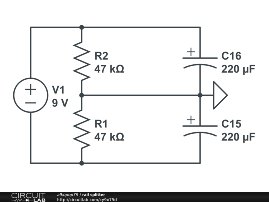
I'm not planning a super high gain circuit, so I imagine +/- 4v should be enough.
Edit: I've got another question:
If I'm using active filters, is there any advantage to using a separate gain stage for the clipping, or would it be just as effective to do the filtering in the clipping stage? I suppose it would be easier to manipulate the cutoff frequencies and the gain if they were in separate stages, but I'd like to limit the number of IC's I use on my board, in order to save space.
If all else fails, I'll use a charge pump in the final design to get +/- 9v. Or I could try this:
I'm not planning a super high gain circuit, so I imagine +/- 4v should be enough.
Edit: I've got another question:
If I'm using active filters, is there any advantage to using a separate gain stage for the clipping, or would it be just as effective to do the filtering in the clipping stage? I suppose it would be easier to manipulate the cutoff frequencies and the gain if they were in separate stages, but I'd like to limit the number of IC's I use on my board, in order to save space.
Last edited:
So right now the only issue I have is a phase shift between the two signals (anywhere from 40 to 60 degrees depending, of course, on the frequency). I can see how it affects the waveforms but I don't exactly see any detrimental cancellations.
Is it worth looking into phase correction, using either another gain stage or inductors? Seeing as this is a pedal (with potentially 6 knobs), I'm trying to conserve space.
Will this most certainly have a negative effect on the tone shaping of this pedal or should I just follow through with the prototyping and see if it sounds alright? I'd rather not have to make big changes to the design after I have prototyped it. Small changes, of course, are inevitable.
- Status
- Not open for further replies.