Hi! I am making a 2-way stereo for my small apartment:
Dayton rs100-4 + SB19st-C0004
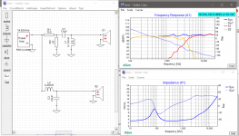
Have never designed a crossover network before, so I would really love to have some feedback on this one, does it seem alright? Will correct baffle step with dsp at later stage.
Thanks in advance!
Kris
Dayton rs100-4 + SB19st-C0004
Have never designed a crossover network before, so I would really love to have some feedback on this one, does it seem alright? Will correct baffle step with dsp at later stage.
Thanks in advance!
Kris
Attachments
Last edited:
It's a good start. I'd move the shunt resistor to next to the tweeter, otherwise it represents a needless consumer of bass energy as heat.
Thanks AllenB! anything else from what you can see with the naked eye? Plan is to do eq with dsp as well, just need a basic crossover as a starting point.
You might want to compensate for baffle step (enlarging the series coil in the lowpass is common). Otherwise, try adding a small value resistor (1Ω) to the lowpass shunt in series with C2. That should lower the output at 3k a bit.
Yes, crossing and EQing is one way to do it, and it can work well.
Ok, so you don't show individual phase on the sim. It's a single angle crossover so there are some things we could look at, but if you can't EQ a satisfactory result then you know to come back to it.
I see the tweeter inductor is a small value, but it's not clear whether this is unnecessarily wasteful without comparing the tweeter with and without it. For that maybe you can pull up the filter transfer function plot.
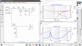
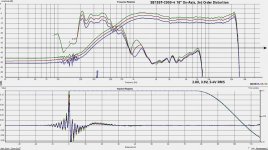
Thanks for all the inputs. Found a bench test of this tweeter, 3rd-order distortion measures suggests 20 db down at 1 khz, so I opted for steeper slope in tweeter filter. Thoughts? Will this work in real life?
Markbakk: Thanks, seemed to do the trick, got som bsc already in the filter now.
AllenB: Thanks, I tried to remove it, it seems to be in the right place. I have not figured out how to show individual phase in this software, not sure if this is possible?
There is this subject of woofer delay. I haven't got the drivers my self yet, so could not measure z-axis differense unfortunately. I guessed 1/3 inch for this sim. Death penaly to not be on spot with this number?
Attachments
Last edited:
You shouldn't concern yourself with delay, unless you are not planning to measure..
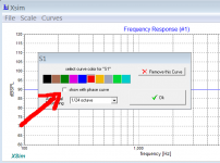
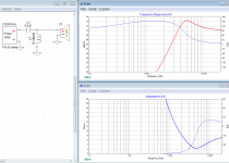
First image shows how to show phase, but will it be correct, did/will you measure?
Second image showing a default driver with a 0.16mH inductor. Q is too high, impedance is too low. You can get the plot I mentioned with the AddGraph button.
First image shows how to show phase, but will it be correct, did/will you measure?
Second image showing a default driver with a 0.16mH inductor. Q is too high, impedance is too low. You can get the plot I mentioned with the AddGraph button.
Attachments
Okay, thank you, I found them both.
Probably will not measure before I buy, no. So I'll leave the delay then.
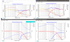
I have attached the picture including spl/frq graph, and the filter response graph, with and without the 0.16mh cap. From what I can read with very limited understanding, it seems to do ok with the cap?
Probably will not measure before I buy, no. So I'll leave the delay then.
I have attached the picture including spl/frq graph, and the filter response graph, with and without the 0.16mh cap. From what I can read with very limited understanding, it seems to do ok with the cap?
Attachments
- Home
- Loudspeakers
- Multi-Way
- Crossover help