Hello folks,
I have been lurking for a while, reading these forums and such and this is my first post.
I recently decided to go through my first ever speaker build from back in 1998, and replace the old parts with newer higher grade parts, upgrade wiring and more. The main reason I want to figure this out is to reuse the old crossover parts with a second set of those tc120 tweeters, and a different set of woofers to make a desktop speaker. In reviewing the crossover diagram and parts I am now confused...thoroughly. I remember when I commissioned the crossover design, the designer said he had to do some crossover tricks because of the spacing I used between the woofer and tweeter (didn't know any better at the time).
Some notes on the speaker:
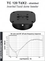
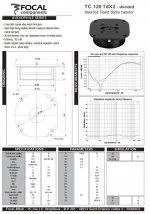
Focal TC120TDX2,
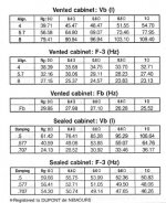
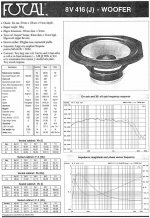
Focal 8V416J
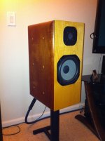
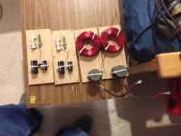
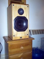
Sealed cabinet ~1cu ft. (I don't recall the exact number, it was 16 years ago 😱 ). In the speaker photo, the space between the woofer/tweeter is actually for a 1" thick divider to separate the tweeter from the woofer.
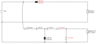
Anyway... when I look at the crossover design, I don't quite understand the crossover points.
Could one of you far more educated designer types take a look and help me understand the reasoning? Does the capacitor pair work on the summed impedence of the tweeter and resistor(28Ω)? The woofer looks to me like its crossed @ ~250hz and the tweeter if at 8Ω would be ~8000hz or if at 28Ω would be ~2500hz?
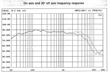
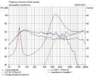
Maybe someone could enlighten me. I do know that the speakers sound fantastic and when he ran them through MLSSA they were +-2db from 20-20000.
Thanks all.
John
I have been lurking for a while, reading these forums and such and this is my first post.
I recently decided to go through my first ever speaker build from back in 1998, and replace the old parts with newer higher grade parts, upgrade wiring and more. The main reason I want to figure this out is to reuse the old crossover parts with a second set of those tc120 tweeters, and a different set of woofers to make a desktop speaker. In reviewing the crossover diagram and parts I am now confused...thoroughly. I remember when I commissioned the crossover design, the designer said he had to do some crossover tricks because of the spacing I used between the woofer and tweeter (didn't know any better at the time).
Some notes on the speaker:
Focal TC120TDX2,
Focal 8V416J
Sealed cabinet ~1cu ft. (I don't recall the exact number, it was 16 years ago 😱 ). In the speaker photo, the space between the woofer/tweeter is actually for a 1" thick divider to separate the tweeter from the woofer.
Anyway... when I look at the crossover design, I don't quite understand the crossover points.
Could one of you far more educated designer types take a look and help me understand the reasoning? Does the capacitor pair work on the summed impedence of the tweeter and resistor(28Ω)? The woofer looks to me like its crossed @ ~250hz and the tweeter if at 8Ω would be ~8000hz or if at 28Ω would be ~2500hz?
Maybe someone could enlighten me. I do know that the speakers sound fantastic and when he ran them through MLSSA they were +-2db from 20-20000.
Thanks all.
John
Attachments

Can you post an image of the network please? This design as it is makes no sense unless there's a hidden midrange that we're not seeing. I'm also extremely skeptical that this system will get anywhere near 20Hz in a sealed enclosure.
Last edited:
I nearly fell off my chair when I ran that filter through my Sim Program! 😀
Weirdest thing. That bass filter does next to nothing. The tweeter filter is your usual first order jobbie.
So what I think you have there, is a polycone bass that runs fullrange, and a highly efficient metal tweeter that gets little filtering.
Last time I saw something like that, it was the Epos ES11 and 14 speakers: Epos ES 14 loudspeaker | Stereophile.com
So you can lose the bass filter altogether IMO. The tweeter filter could be improved from the joke 1st order type though. A series crossover with some good slopes on the tweeter would work very well here IMO.
Attachments
John,
A very unusual filter you have there. There appears to be a typo in the
tweeter section. Capacitors with mH! 15 mH could also be a typo or not.
1,5 mH would be more appropriate. XO frequency could be better(lower)
though. Since I have no better files to work with, let's pretend this not to be
such a bad approximation.
Attachments
That Phoenixnoir link isn't working for me, Pete. This is better I think:
Le Phenix Noir : Le Coin de l'Audiophile > Base HP. Nice database of obscure drivers. 🙂
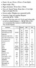
Focal make car speakers mainly, don't they? These two are pretty conventional high quality units though. 8" 88dB Le=1.2mH 5R reflex Polyglass woofer apparently. High efficiency 95dB 1" 0.09mH 6R titanium ferrofluid tweeter.
Akhnot, hate to tell you this, but your filter is just plain awful. You can get this sounding much better. You're listening to some terrible distortion right now.
If you want to build some desktop speakers, that is another design too, depending on the bass you choose.
Attachments
That's why I want to see a picture of the network itself, because this bad boy makes zero sense.Akhnot, hate to tell you this, but your filter is just plain awful. You can get this sounding much better. You're listening to some terrible distortion right now.
If you want to build some desktop speakers, that is another design too, depending on the bass you choose.
That's why I want to see a picture of the network itself, because this bad boy makes zero sense.
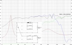
It makes a sort of sense with an unusual woofer downwards slope there. But it's still strictly a Mickey Mouse filter. Too much cone breakup around 5kHz from the bass, and an overdriven tweeter.
I roughly corrected the electrical for the woofer's significant 1.2mH inductance, and gave the coil 2 ohms resistance. It's almost like the woofer has built-in bafflestep. Quite unusual. And hard to believe you'd use a 15mH coil. Must cost a fortune!
Attachments
Oops, when I put that into Visio I did put mh instead of uF, the values are correct though. So, I'll restate that he told me he had to do some funny stuff with the crossover to make them sound right. I did request 1st order filters so that's why they are very minimal component.
Anyway, I don't want to mess with those just trying to understand, and apparently unless I go back and look up the folks from the now defunct Speakers Etc... I'll never know exactly what his logic was. He did design these by ear using music, and I have (somewhere) the MLSSA paper strip from when we measured them.
I may break into them again at some point and try some more traditional crossover slopes.
I will consult again when the new bass drivers arrive for the new desktops.
Thank you all for confirming that I wasn't crazy in not understanding these. It must FM. 😉
Oh, System7, Focal is JM Labs. They broke into the car market, but they are mainly higher end.
While measuring is not strictly necessary, using unpredictable dynamic material to voice a speaker is guaranteed to result in a failed design unless you have a perfect reference. You cannot account for the speaker's broadband behavior when the signal is not either a noise spectrum, or memoryless like a sine wave. In other words, you must know exactly what is going into the speaker to understand how the speaker changes the input.Oops, when I put that into Visio I did put mh instead of uF, the values are correct though. So, I'll restate that he told me he had to do some funny stuff with the crossover to make them sound right. I did request 1st order filters so that's why they are very minimal component.
Anyway, I don't want to mess with those just trying to understand, and apparently unless I go back and look up the folks from the now defunct Speakers Etc... I'll never know exactly what his logic was. He did design these by ear using music, and I have (somewhere) the MLSSA paper strip from when we measured them.
I may break into them again at some point and try some more traditional crossover slopes.
I will consult again when the new bass drivers arrive for the new desktops.
Thank you all for confirming that I wasn't crazy in not understanding these. It must FM. 😉
Oh, System7, Focal is JM Labs. They broke into the car market, but they are mainly higher end.
Very interesting really, Akhnot. Your friend has done a decent job of designing a LR2 12dB/octave filter there. Normally that would wire negative polarity, but the time-alignment error makes it wire positive polarity.
But people like KEF never used such simple filters even with well behaved woofers. You really need steeper slopes to get rid of the nasties which start at 3kHz upwards on the woofer.
Gentle 2nd order on 8" bass, and third or fourth order tweeter filter wired negative polarity and around 3kHz works a treat. It will transform your speaker. 😎
But people like KEF never used such simple filters even with well behaved woofers. You really need steeper slopes to get rid of the nasties which start at 3kHz upwards on the woofer.
An externally hosted image should be here but it was not working when we last tested it.
Gentle 2nd order on 8" bass, and third or fourth order tweeter filter wired negative polarity and around 3kHz works a treat. It will transform your speaker. 😎
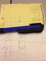
I did manage to find the Focal driver specs, and a photo of the physical networks from when I did the rebuild a few weeks ago. I think all the requested items are now attached to this thread. I still had all of the papers in my old binder from back then, along with the receipts, and the hand drawn schematic.
My wife thinks I should rebuild the cabinets moving the drivers to the correct spacing and then re-do the crossovers. I enjoy the sound, so not anxious to do that, but... maybe someday. I have too many hobbies and home projects going right now to take on that project. 😀
My wife thinks I should rebuild the cabinets moving the drivers to the correct spacing and then re-do the crossovers.
I enjoy the sound, so not anxious to do that, but... maybe someday. I have too many hobbies and home projects going right now to take on that project. 😀Attachments
So there is no problem? Good! One day your tweeter surrounds will
deteriorate. Then you might redo things, depending😉.
Akhnot, you've been a fun guy here. You had us scratching our heads at first, but I see where you're coming from. It happens that 8" bass plus tweeter is my favourite subject. 😀
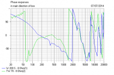
I see nothing wrong with your cabinets at all. But I should explain what is wrong with 12dB/octave LR2 filters with 8" bass. It's the time alignment error of about 5cms due to the deep bass chassis, which kill any decent phase alignment. 😕
What you need is the theoretically near perfect LR4 or 24dB/octave:
Now everything works. I'll be a tease and withold the elegant circuit here, mainly because I don't feel I'm getting enough love from the forum lately, and why give it away if they don't appreciate it. But it performs like this. Lovely! It's as good as it gets. 🙂
I see nothing wrong with your cabinets at all. But I should explain what is wrong with 12dB/octave LR2 filters with 8" bass. It's the time alignment error of about 5cms due to the deep bass chassis, which kill any decent phase alignment. 😕
What you need is the theoretically near perfect LR4 or 24dB/octave:
An externally hosted image should be here but it was not working when we last tested it.
Now everything works. I'll be a tease and withold the elegant circuit here, mainly because I don't feel I'm getting enough love from the forum lately, and why give it away if they don't appreciate it. But it performs like this. Lovely! It's as good as it gets. 🙂
Attachments

Ok. I just fired myself. 
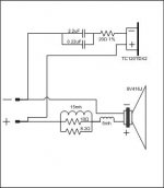
Maybe this corrected version of my Visio makes more sense? lol
I just got home from work, and opened up the diagram to correct the uf/mh typo and noticed that one MAJOR component is not in there. The actual woofer crossover 5mh coil. 😱
So... I added that in, fixed the typo, cross checked it against the hand drawn diagram. I'm also posting the original diagram from 1998 just in case I missed something else. The tweeter crossover is connected to the negative, is that what you were referring to S7?
Now, I still don't understand the crossover points, because the woofer seems too low to me, but maybe baffle interaction, and slow tweeter slope make up for it in a 6db 1st order.
Well, now I am going to crawl in a hole in shame.
Thanks all for scratching your heads, maybe this will work for some salve and my original lesson request can begin in earnest. =/
Attachments
John,
get some measurement gear, free software, some parts and rebuild the
filter. This one makes no sense, especially now with 5 mH. When your
gear is up and running, you would need a couple of hours working on it
to make it really a good one. I can't figure out how your current setup
could measure within 2dB throughout the range.
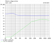
I don't think you need any measuring gear with such a simple speaker, with so few adjustments!
As it is, efficiency is terrible. And everything else unusual too. But power delivery is surprisingly even, and phase alignment good from 3-5kHz.
But you can do better. Forget the silly low order filter dogma, this is a case where a simple filter works worse than a higher order one. Why? Because the bass rolls off steeply anyway. Way more than 6db/octave acoustic.
Attachments
Akhnot, you asked for a better circuit to try. 🙂
This really had me scratching my head, because the bass looks like it can free-run without a filter at all. And the metal tweeter is quite efficient at 92dB.
What I've come up with is NOT boring old Linkwitz-Riley LR4 or the dreadful shallow LR2, it's what we call an acoustic butterworth filter or BW3. It has nice flat power response via a rather perplexing 90 degree phase mismatch. Which means good dispersion off axis. It sounds very nice and works particularly well with an 8" bass.
I really don't know if you'll need the bass coil at all. If the sound is lacking in bass, than you will. Usually we'd use 1.5mH, but your bass is unusual. The tweeter filter is set in stone, but the red attenuator might need some adjustment.
This is DIY, so you might want to fiddle with it a bit. But I think it's worth a go. Definitely high fidelity. It's what the BBC used to do when building speakers. But a livelier paper bass rather than a polycone. Don't go crazy on expensive components. It is not a demanding circuit. A ferrite on the bass, and 250V or 400V polypropylene caps, and an air coil on the tweeter. Put the coils at 90 degrees relative to each other too.
I'd stock up with some pairs of 10W wirewound or ceramic resistors too. 2.2R, 3.3R, 3.9R, 4.7R, 6.8R, 8.2R, 10R, 15R, 22R, 33R. They are cheap. Tweeter level is fussy! Get a couple of 0.68uF capacitors too, so you can try a Zobel on the tweeter.
Good luck, my friend. I want to hear how this turns out. 😎
Attachments
- Status
- Not open for further replies.
- Home
- Loudspeakers
- Multi-Way
- Crossover dissection assistance, help please :)