My dad replaced some worn out drivers in some old thrift store boxes with some inexpensive stuff from parts express. He just dropped them into the box on the old crossover and away he went.
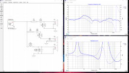
Not a fan of the sound, I wouldnt have called it warm, neutral, or bright, weirdly enough, and i know how picky crossovers can be. Made some files from the charts for the grs/dayton drivers he chose, and simulated it with the crossover thats in there, thats PIC#1. The Crossover like an off the shelf job someone used to replace a single woofer inductor/tweeter cap(hanging loose in box still lol). the 400-700hz peak is very audible and it's what had me messing with xsim. I left the individual driver curves out because its an absolute mess, i couldnt even tell you what the crossover points are looking at it. It was bad, very very bad.
The second series resistor on the mid range is a variable potentiometer he wants to keep, and honestly it helps me out anyway.
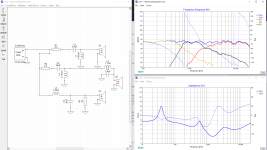
I have a decent understanding of what im doing, but pretty novice with crossovers in practical application. Pic #2 is the flattest freq response, phase, and impedance i can muster after many hours of tweaking values. (im kinda shocked i got it that flat, there's a $7 sealed back GRS midrange, and $19 grs woofer in there, def the two hardest to make work drivers ive played togetherwith in xsim, Crossover points about 680hz/2.2khz, from like 1400hz and, idek, 10khz? They basically ran together from 10khz all the way to 16khz 🤷♂️
Being a novice that hans't ever built a crossover from scratch, just lightly modified existing ones, and tinkered with Xsim time to time in curiosity, Is there any obvious reason im overlooking that i shouldn't build this crossover, or something else i need to change in it before its worth building? These were thrift store speakers, far from his main system, and my dad has no attachment, so i have free range to tinker and learn. Stock xover is all electrolytic caps too, id be using (mostly) film.
Pic#1 Current xover

#2

Not a fan of the sound, I wouldnt have called it warm, neutral, or bright, weirdly enough, and i know how picky crossovers can be. Made some files from the charts for the grs/dayton drivers he chose, and simulated it with the crossover thats in there, thats PIC#1. The Crossover like an off the shelf job someone used to replace a single woofer inductor/tweeter cap(hanging loose in box still lol). the 400-700hz peak is very audible and it's what had me messing with xsim. I left the individual driver curves out because its an absolute mess, i couldnt even tell you what the crossover points are looking at it. It was bad, very very bad.
The second series resistor on the mid range is a variable potentiometer he wants to keep, and honestly it helps me out anyway.
I have a decent understanding of what im doing, but pretty novice with crossovers in practical application. Pic #2 is the flattest freq response, phase, and impedance i can muster after many hours of tweaking values. (im kinda shocked i got it that flat, there's a $7 sealed back GRS midrange, and $19 grs woofer in there, def the two hardest to make work drivers ive played togetherwith in xsim, Crossover points about 680hz/2.2khz, from like 1400hz and, idek, 10khz? They basically ran together from 10khz all the way to 16khz 🤷♂️
Being a novice that hans't ever built a crossover from scratch, just lightly modified existing ones, and tinkered with Xsim time to time in curiosity, Is there any obvious reason im overlooking that i shouldn't build this crossover, or something else i need to change in it before its worth building? These were thrift store speakers, far from his main system, and my dad has no attachment, so i have free range to tinker and learn. Stock xover is all electrolytic caps too, id be using (mostly) film.
Pic#1 Current xover

#2

Last edited:
It is, kind of, but not really.
Without that resistor the output of the woofer is a bit.... rounded in response, and i can attenuate it with a low value series resistor, but it stays round and rolls off sooner down low and creates a valley at the woofer/mid crossover point i cant fix with the filters, im assuming because it changes the pass filter more dramatically then a high value parallel resistor., which flattens the response as well as attenuates slightly. The parallel resistor also seems to affect phase accuracy less then the series did on the woofer. But just an educated guess, im only loosely know what im doing.
If there is a better way to achieve that result i just don't know about it. The response of this cheapo woofer is so wonky i couldnt do it with the pass filters nearly as effectively on the woofer or midrange with series resistance, their natural response is all over the place (its honestly the worst freq and impedance curve ive ever seen on a midrange driver, woofer not far behind, but hey, it was apparently $7 and $19 respectively). That parallel resistor just happened to have the effect i was after according to the simulation lol
Thanks though, first crossover build i wanted to make sure i hadn't done, or overlooked anything too stupid, very easy to do in the audio world. I wasn't even totally sure i've been reading the graphs correctly, good to know i am!
Once i build it ill do a listen test with and without that resistor though, it was the very last tweak i added to it anyway. it did more flattening the center of the response curve then attenuation of output though. I dont posses enough knowledge to know why. It did also have a very desirable effect on the overall system impedance curve too. Especially down low.
Last edited: