So here the deal! Im building a 4-way Floorstander and ive ran into an issue with impedance. My issue is, im working with 4-8 ohm speakers and if i run them all in parallel i will end up somewhere around 1-2 ohms (just a guestimation). Wont this be bad for my amplifier? As a solution, i would just wire the two LF drivers in series and wire the two HF drivers in series, but then how do i design the crossover so that each speaker plays a specific frequency range? I only understand how to wire crossovers for each speaker when they are done in parallel.
When crossed, the woofer and tweeter aren't in parallel because they don't play together significantly at any frequency.
Could you describe your configuration...
Could you describe your configuration...
The crossover increases the impedance seen by the amplifier outside of each driver's pass band.
For example, the woofer usually has a series inductor, and the tweeter usually has a series capacitor.
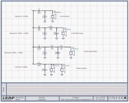
Three and four ways get more complex. Here's one fourth order crossover chosen at random.
For example, the woofer usually has a series inductor, and the tweeter usually has a series capacitor.
Three and four ways get more complex. Here's one fourth order crossover chosen at random.
Attachments
Last edited:
Oh my gosh i never thought about that! Also not sure to what exactly you’re referring to with my “configuration” but I’ll do my best.When crossed, the woofer and tweeter aren't in parallel because they don't play together significantly at any frequency.
Could you describe your configuration...
1x 15” Subwoofer LR2 XO at 80hz LPF
1x 6” Woofer LR2 XO at 600hz LPF (im letting it naturally roll off into the sub)
1x 4” Mid LR2 XO at 600hz and LR3 XO at 2.5 kHz BPF
1x AMT tweeter LR3 XO at 2.5 kHz
Everything is in a sealed enclosure. Sub and woofer have dedicated separate enclosures and the mid and tweeter will share an over all smaller enclosure on top of the woofer and sub to minimize the width of the front baffle around the tweeter.
What you have sounds good. I was thinking about when you said put the two highest in series and still get them separated with the crossover but I see you're not planning that. (It still is possible but not necessary). I also see you'll have the two woofers in parallel below 80Hz. It may be fine, what are your thoughts on simulating it?Also not sure to what exactly you’re referring to with my “configuration”
I suppose you mean simulating it on xsim? I havent gotten to that yet but that would be my next course of action. Not sure if that answers your question?What you have sounds good. I was thinking about when you said put the two highest in series and still get them separated with the crossover but I see you're not planning that. (It still is possible but not necessary). I also see you'll have the two woofers in parallel below 80Hz. It may be fine, what are your thoughts on simulating it?
Sure, when you're ready. It would help to answer the question of the overall impedance, and to better manage the impedance peaks.
If simulating also try a simple first order XO for the 15" woofer.
What drivers are you thinking about or already purchased?
What drivers are you thinking about or already purchased?
There are quasi alignments like Jon Marsh also uses, but I remain steadfast in my position otherwise.
You really want a LPF on the 6 inch woofer. You avoid alot of distortion when you roll off the signal below useful output.
Also you may want to see if there is any way to bi-amp this. Parts for a passive 80 HZ crossover get sort of large and lossy.
Also you may want to see if there is any way to bi-amp this. Parts for a passive 80 HZ crossover get sort of large and lossy.
A Bessel 3rd order with an offset frequency is a nice substitute.There are quasi alignments
Thats actually another thing i was curious about. Would electrolytic caps and iron core inductors have much effect at a sub 80hz range? I was under the impression that the smearing effect created by these parts would be less apparent at these frequencies.You really want a LPF on the 6 inch woofer. You avoid alot of distortion when you roll off the signal below useful output.
Also you may want to see if there is any way to bi-amp this. Parts for a passive 80 HZ crossover get sort of large and lossy.
I was under the impression that an LR XO just meant a -6dB dip at the XO point to result in a flat sum? I was also under the impression that crossover orders correlated with the parts count. 1st order is 1 component, 2nd order is 2 etc. please correct me where im wrong.LR are even order xovers, so there is no LR3.
I tried the first order and it didnt roll off how i liked. As for drivers i have purchased/ am thinking ofIf simulating also try a simple first order XO for the 15" woofer.
What drivers are you thinking about or already purchased?
15” dayton rss390hf-4
6” dayton reference paper 8 ohm
4” tang band w4-1320sj
AMT2-4 Dayton audio
One of the main issues I am running into is there are no ZMA, FRD files for the Tang band driver
Modeling or listening? Sometimes there is a difference and when using the first order was it as a .5 driver wth the 6" dayton running open at the bottom end?
To me the driver combination is screaming Bi-Amp at around 100 / 120
To me the driver combination is screaming Bi-Amp at around 100 / 120
Butterworth -3dB also results in a flat response as well as flat power. -6dB has a power dip.-6dB dip at the XO point to result in a flat sum?
Summation "in phase" to flat response, as well as -6dB at summation is the LR way. These should always be even order acoustic slopes.I was under the impression that an LR XO just meant a -6dB dip at the XO point to result in a flat sum? I was also under the impression that crossover orders correlated with the parts count. 1st order is 1 component, 2nd order is 2 etc. please correct me where im wrong.
BW phase is 90° out of phase between drivers.
If the slope matches the order, say 12dB/octave acoustic, then it is second order. If it's in phase and -6dB at xover, then it's an LR2.
If it matches 18dB/Oct, -3dB at xover, and 90° out, then it's a BW3.
Textbook equations asign certain Q to the curve, but once applied to imperfect sloping drivers' responses, these numbers will change to enact proper filtering.
Depending on the ripple to either side of the xover, and the damping of the knee, this can equate to other named topologies, but for maximally flat response, usually the 3 used are BW, LR, and Bessel.

I tried the first order and it didnt roll off how i liked. As for drivers i have purchased/ am thinking of
15” dayton rss390hf-4
6” dayton reference paper 8 ohm
4” tang band w4-1320sj
AMT2-4 Dayton audio
One of the main issues I am running into is there are no ZMA, FRD files for the Tang band driver
What electronics are using? If using a typical AVR, I would use the built-in sub crossover to cross (and level match) the sub to the 6". Otherwise you will have really big crossover costs for no good reason. And you would lose sensitivity. So think 3-way crossed to a sub.
- Home
- Loudspeakers
- Multi-Way
- Crossover design problem