The shapes of the filter transfer functions that can be realized with simple linear L, C and R parts are just what algebra of the L, C and R impedance gives us. Rearranging the L, C and R parts in the xover in unusual ways will not open any "new windows" to previously impossible transfer functions.
However, adding a loudspeaker to the mix might change this a little bit (but not much). The impedance of a real-world loudspeaker usually cannot be not fully represented by a bunch of linear L, C and R parts. These non-linearities of the loudspeaker impedance involve some deviations from "linear L/C/R algebra", which in turn might allow transfer function shapes that do not exist with the "conventional" x-over topologies. Yet, the loudspeaker non-linearities are not huge, so don't expect any game changing new transfer functions.
I guess Troels' motivation to use this "unconventional" topology is just to do stuff in a different way, to stand out from the crowd. The electroacoustics are the same.
The electroacoustics are the same.
No, they have changed a little.
The C3 high pass to ground has been taken outside the main C4 high pass.
It tilts the FR towards more lower output.
I believe you misunderstood my point. I was trying to say that the "new" xover circuit topology does not offer any (substantially) new types of filter transfer functions.
The change in the transfer functions of Troels MKII version could have been achieved using the conventional circuit topology.
The change in the transfer functions of Troels MKII version could have been achieved using the conventional circuit topology.
what is the behavior of the Gnd return path on the tweeter and mid that have a cap on their path ? Never seen that, does it smooth the entire impedance curve of each driver ?
thanks.
So with the driver coil resistance in serie, it's a zobel that smooths on all the entire frequency band window of the driver ?
* about TG, each of his newest loudspeakers are said to be the best ever he has made, it's a little commercial sided, but it doesn't say it sounds bad... you just don't know if it is really better than the previous ! If it was perhaps he would have edited for a new filter for the previous 3WCs with the perhaps better on the notice SS 10F... He already made a phase 2 ScanSpeak 3WC with a Revelator woof and the same mid that this new design, iirc ! I can not imagine the Discovery woof that is good average everywhere without to be sota to paraphrase Zaph, can be better than a Revelator with its very low Fs and of course better motor and distorsion number in the mid frequency where the cut-off is. The tweeter is certainly better with the new design than this phase 2 he made with what he had on hands ! But you have to listen to it to know in real life imho...
What begins not to be new is that the filter is costing more than the drivers...
I have also a little pain with the Way Classic shortcut as in my language it means Water closed for toilets ! But I personally like their look very much and I'm making myself just for the fun a basic 3 WC with the Harbeth looking... so, TG is still inspiring..
Last edited:
what is the behavior of the Gnd return path on the tweeter and mid that have a cap on their path ? Never seen that, does it smooth the entire impedance curve of each driver ?
It isn't ground as such. It's just referred to as that. Audio is AC. Providing the electrical topology of the circuit remains the same, you can put series components in either the nominal + or - leg since it's just part of the same circuit.
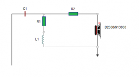
ProAc have done this since woolly mammoths roamed the Earth. I've sometimes done it myself, partly to illustrate the above point to my cabinet-building partner in crime, but also because sometimes it can be more convenient to lay out a circuit board / breadboard / whatever. In topology, TG's HF circuit for example is a damped 2nd order electrical followed by a padding resistor. If you want to redraw it, just put C1 in series with the driver in the nominal + leg ahead of the R1 L1 shunt.
Last edited:
Yes, thanks Scott to correct my words, my bad,
Indeed one must NOT putt a cap in serie between a main and the Earth Ground for security purpose. I should have said "Return path" in that loudspeaker context.
Indeed one must NOT putt a cap in serie between a main and the Earth Ground for security purpose. I should have said "Return path" in that loudspeaker context.
Just so, although strictly speaking there isn't really a fixed 'return path' either (which was the real point I was making) since it's AC. The signal travels back & forth, not in one direction. That's why in a parallel circuit you can put series components in what for convenience is described as the - leg, providing the topology is maintained, as Troels has done here, ProAc invariably do, & others as whim or convenience strikes. 😉
This is the HF circuit-leg redrawn in a more commonly seen format:
This is the HF circuit-leg redrawn in a more commonly seen format:
Attachments
Last edited:
Yes, I've done it this way. It was so long ago I'm not sure when exactly.woolly mammoths

........... as Troels has done here, ProAc invariably do, ..........)
How is this Proac model similar to this 3-way project ? I've heard the two-way 125 and it didn't really strike me as anything special.
I remember its owner excitedly exclaiming "listen to that guitar!" .........
Yes, from 1 meter away it was a nice sound, although it was not an acoustic guitar, it is difficult to evaluate the real tone of an instrument like that.
It was a DSOTM song, of Pink Floyd.
Attachments
Nothing in terms of driver configuration. As noted, I was referring to the filters: ProAc invariably place (or used to place) all the series components in their crossovers in the notional negative leg, rather like Troels has done with his C1 and C4 HF & midrange capacitors. There is no electrical or acoustic advantage to doing so, it's a parallel AC circuit, but it may in somes cases make physical component layout more convenient. It just looks a bit different and catches attention when the circuit diagram is drawn. Especially if you draw it with what for some might be a visually unusual layout.
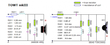
Got it, thanks Scott. It strikes me that Troels no longer indicates the resistance values introduced by the coils. ( see attached R 2011)
I imagine that this can only matter for the very precise calculation of the low frequency section ....., but I have not seen it in his recent work "The Loudspeaker" either.
Is it that he does not consider it more important or does not come out drawn but is contemplated in the calculations?
This "virtual" value is not seen in "open" works by other designers.
I suppose it is in order not to confuse kit buyers, who may claim the lack of that component ...😀
A digression here:
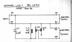
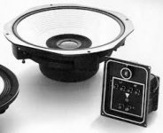
My vintage JBL LE14C does not have a low pass coil, and some people have mentioned to me that "that is poorly designed", and that adding it would improve the overall performance. (the sound is typically somewhat lacking in mids, there is a little hole there)
But it is very common in two-way cabinets to block only LF in the tweeter.
The
Typical corrugations in large diaphragms have a double purpose, to give rigidity to it to favor the piston effect, but also, - when they do not reach the center of the voice coil, leaving a smooth sector - it favors the medium frequencies, it is a purely "mechanical" filter.
With that said, would you improve the mids by adding a coil on the twoofer / midrange? I think not, because it would also block the mid frequencies.
Does anyone think that some modification can improve this lack - very subjective - of the mid-range?
I imagine that this can only matter for the very precise calculation of the low frequency section ....., but I have not seen it in his recent work "The Loudspeaker" either.
Is it that he does not consider it more important or does not come out drawn but is contemplated in the calculations?
This "virtual" value is not seen in "open" works by other designers.
I suppose it is in order not to confuse kit buyers, who may claim the lack of that component ...😀
A digression here:
My vintage JBL LE14C does not have a low pass coil, and some people have mentioned to me that "that is poorly designed", and that adding it would improve the overall performance. (the sound is typically somewhat lacking in mids, there is a little hole there)
But it is very common in two-way cabinets to block only LF in the tweeter.
The
Typical corrugations in large diaphragms have a double purpose, to give rigidity to it to favor the piston effect, but also, - when they do not reach the center of the voice coil, leaving a smooth sector - it favors the medium frequencies, it is a purely "mechanical" filter.
With that said, would you improve the mids by adding a coil on the twoofer / midrange? I think not, because it would also block the mid frequencies.
Does anyone think that some modification can improve this lack - very subjective - of the mid-range?
Attachments
Last edited:
You can have a hole because it beams, or worse. This measures well (when not measured properly) but sounds bad. If you use a low pass filter, you will also need to have the tweeter go lower, or add a mid.
Beams = It is loud at the front, if you measure from the front it looks good, but there is less sound into the room. The driver cannot work equally with a dome at these frequencies, you want to cross lower.
It's comparable to light. You can have flood light that evenly spreads out in a room and there's spot light that focuses on the spot, leaving other places dark. A loudspeaker acts as a flood light at low to middle frequencies, but most speakers act as a spot on high frequencies. That is no problem in itself, as long as the transition from flood to spot is gradual.
Two way systems however often display a frequency region where the bass-mid starts beaming as a spot, whereas a little bit higher the tweeter comes in, flooding all over the place. Think of this to happen at the typical crossover region of the speaker. This leads to an uneven sound balance, because of the sudden excess reflected sound energy in the higher frequencies, just where the sound energy started to drop courtesy to the bass-mid.
We almost always address the beaming of a loudspeaker with the directivity index, or DI. A major design goal for a good loudspeaker is a with frequency change gradually changing or constant DI. Not one with sudden drops or rises.
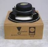
Ops, it's a coax, my fault, sorry, I should have mentioned this before....😱
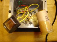
From what I am told, I deduce that there is no improvement by modifying adding a block coil to the high mids and highs to this "simple" cross over. Actually I did a modification a few years ago, I replaced the original JBL caps (PIO) by Clarity Cap Esa, I noticed a more detailed sound, but maybe that modified the tone of the midrange.
I did the two "upgrades" simultaneously, so I couldn't compare them, that was a mistake, but I don't see much sense to go back to working on the original xovers, they are very difficult when being in closed boxes. (Although I could experiment to compare the sound, putting together a just new xover with Clarity Cap capacitors and an air core coil instead of iron, but this one would be too big! Anyway, thanks for your input, if there are more, they are welcome.
OT :
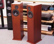
These speakers were the wedding gift of an aunt of my wife (Teresa, she was a great person, she was very funny even though she had not had an easy life, it is a compensation that a few very special beings have), she lived in New Jersey and traveled several times to his native country, she asked us what we wanted as a wedding gift .....
I remember when we went to look for her at the airport - in 1978 - and she saw me, she told me:
"Boy, you could have chosen something less heavy" 😀
From what I am told, I deduce that there is no improvement by modifying adding a block coil to the high mids and highs to this "simple" cross over. Actually I did a modification a few years ago, I replaced the original JBL caps (PIO) by Clarity Cap Esa, I noticed a more detailed sound, but maybe that modified the tone of the midrange.
I did the two "upgrades" simultaneously, so I couldn't compare them, that was a mistake, but I don't see much sense to go back to working on the original xovers, they are very difficult when being in closed boxes. (Although I could experiment to compare the sound, putting together a just new xover with Clarity Cap capacitors and an air core coil instead of iron, but this one would be too big! Anyway, thanks for your input, if there are more, they are welcome.
OT :
These speakers were the wedding gift of an aunt of my wife (Teresa, she was a great person, she was very funny even though she had not had an easy life, it is a compensation that a few very special beings have), she lived in New Jersey and traveled several times to his native country, she asked us what we wanted as a wedding gift .....
I remember when we went to look for her at the airport - in 1978 - and she saw me, she told me:
"Boy, you could have chosen something less heavy" 😀
Attachments
Last edited:
- Home
- Loudspeakers
- Multi-Way
- Crossover current by 3WC mkII by Troels, opinions ?