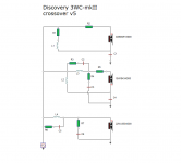
" Some of you interested in crossovers may find the current 3WC mkII crossover intriguing and I look forward to your response. "
Speaker Talk
25th February 2021
This is a recent question from Troels for his readers.
I have experience in assembling boxes, but not in calculating crossover networks. Although today there are programs that help a lot in this task, but, I consider that experience is essential.
So the table is set, you just have to sit down to eat ! 🙂
Sorry, can’t answer the OP’s question but also noticed that the crossover values for the SBA761 and SBA741, which were previously open designs, have been removed. Anyone know why unless they started to become popular so kits were worth making exclusive/closed (looks like there are around 10 SBA761 built on his site) but the cat is out of the bag as I have seen the SBA761 crossover posted on a couple of sites.
I have yet to simulate this kind of crossover and see what it does. For sure the bass LP filter is pretty normal.
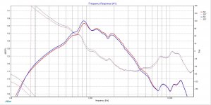
However I really don't care anymore for any recent TG design. Evidently his desire to monetize has forced him to follow new routes from what he was doing some years ago (when his designs were open). So he found this LR2 "holy grail" crossover approach, and praise it, but for doing so he went with the stepped baffle road with the inherently diffraction problem. He doesn't provide real measurements anymore except for an on-axis FR, evidently with off-axis FR it would be evident that the stepped baffle introduce anomalies in the FR and thus a poor power response.
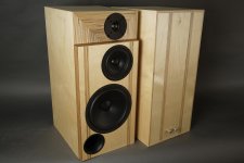
For this particular design there is another bad point. You can't have a 88dB speaker with a 89dB woofer, unless you are cheating or aren't providing a reasonable baffle step compensation (or both).
Ralf
However I really don't care anymore for any recent TG design. Evidently his desire to monetize has forced him to follow new routes from what he was doing some years ago (when his designs were open). So he found this LR2 "holy grail" crossover approach, and praise it, but for doing so he went with the stepped baffle road with the inherently diffraction problem. He doesn't provide real measurements anymore except for an on-axis FR, evidently with off-axis FR it would be evident that the stepped baffle introduce anomalies in the FR and thus a poor power response.
For this particular design there is another bad point. You can't have a 88dB speaker with a 89dB woofer, unless you are cheating or aren't providing a reasonable baffle step compensation (or both).
Ralf
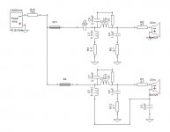
Some sections are inverted, but they function the same.I have yet to simulate this kind of crossover and see what it does.
Sorry, can’t answer the OP’s question but also noticed that the crossover values for the SBA761 and SBA741, which were previously open designs, have been removed. Anyone know why unless they started to become popular so kits were worth making exclusive/closed (looks like there are around 10 SBA761 built on his site) but the cat is out of the bag as I have seen the SBA761 crossover posted on a couple of sites.
Troels is a designer of audio cabinets and he makes his money on it. I don't see what's wrong with that. Another thing is to be silly and allow others to copy your designs to market them as their own, that is plagiarism and illegal. There was enough talk about it on this forum.
I have yet to simulate this kind of crossover and see what it does. For sure the bass LP filter is pretty normal.
However I really don't care anymore for any recent TG design. Evidently his desire to monetize has forced him to follow new routes from what he was doing some years ago (when his designs were open). So he found this LR2 "holy grail" crossover approach, and praise it, but for doing so he went with the stepped baffle road with the inherently diffraction problem. He doesn't provide real measurements anymore except for an on-axis FR, evidently with off-axis FR it would be evident that the stepped baffle introduce anomalies in the FR and thus a poor power response.
For this particular design there is another bad point. You can't have a 88dB speaker with a 89dB woofer, unless you are cheating or aren't providing a reasonable baffle step compensation (or both).
Ralf
The diffraction is the same as the phase delay? (hence the stepped baffle, to compensate for the LR2 filter, I just repeat what he said) LR is Linkwitz Riley, I guess Troels must have read it ...
" Much is hypothesized, little is proven and much is overrated when it comes to diffraction. "
Diffraction from baffle edges
Is there anything you didn't understand in what I wrote? Just to make it clear, a LR2 acoustic crossover (Linkwitz-Riley 12db/octave roll-off), provides a flat sum between drivers. Unfortunately due to the wavelength at a typical crossover frequency between a mid and a tweeter, and to the fact that the voice coil of a mid is more recessed in respect to a tweeter (*) to implement a LR2 crossover you need one of these tricks:
1) a phase delay in the crossover
2) a tweeter in a waveguide
3) a slanted baffle (with the right angle)
4) a stepped baffle (with the right step depth)
Apart the delay network that imposes a complicated crossover IMHO the best approach is the waveguide, followed by the slanted baffle.
The Linkwitz article is about the effect of a flat baffle. Not about the (additional) effect of the diffraction imposed by an additional edge right at the tweeter: the wave front coming from the tweeter in this case is a mess of waves with different phases.
Frankly saying good things about LR2 designs and implementing them in a sub-optimal way is kinda strange.
I already said that I really dislike a closed kit where I have to buy overpriced parts (crossover components but not only). However I don't have any problem in buying a plan for a crossover, but I need to be convinced that this crossover does good things (**). The problem lies in the fact that I can't find an evidence of the fact that the crossover creates a good speaker, and that is valid for every recent TG designs. He doesn't provide data to evaluate them, for this speaker he provides only an on-axis FR, no off-axis FR, no reversed mid FR (for evaluating phase coherence between drivers), nothing. You will buy the kit only on faith.
But I see where the TG kits are appealing, he provides lots of advice for the build.
(*) The sound doesn't propagate exactly from the voice coil but more or less the argument holds
(**) See Heissmann Acoustics site for what I mean, just as an example
Ralf
TG's model of business is nothing unseen before. Copy the looks of a reputable high end audio stuff manufacturer and offer a look-alike for a lot less money. In phase one, kits were free of charge, once people started gaining confidence, free kits phase ceased to exist. You can justify it this or the other way. The point is to increase income.
edit: TG website project is a good opportunity for DIY community interested in learning how to build stuff, aside with what we do not agree with.
edit: TG website project is a good opportunity for DIY community interested in learning how to build stuff, aside with what we do not agree with.
Last edited:
What TG does is called an "influencer" in other lines of trade. Ralf hits the nail perfectly with his comments about published curves and LR 2
Yet the x/o component values can be calculated relatively easy in Vituixcad: Use the curve tracer to generate your target curves, then take the .frd and .zma curves of in box drivers used in the design, draw the filter topology in the x/o design function, use "educated guess" starting values and let the Optimizer then do all the dirty work for ya.
Yet the x/o component values can be calculated relatively easy in Vituixcad: Use the curve tracer to generate your target curves, then take the .frd and .zma curves of in box drivers used in the design, draw the filter topology in the x/o design function, use "educated guess" starting values and let the Optimizer then do all the dirty work for ya.
" Some of you interested in crossovers may find the current 3WC mkII crossover intriguing and I look forward to your response. "
Speaker Talk
25th February 2021
This is a recent question from Troels for his readers.
I have experience in assembling boxes, but not in calculating crossover networks. Although today there are programs that help a lot in this task, but, I consider that experience is essential.
So the table is set, you just have to sit down to eat ! 🙂
The oddity for me is the capacitors on the return side of the M and T drivers, with the return for the shunt part of the network going above these capacitors, rather than directly to ground. I've never seen this before, and I would be intrigued to read Troels' explanation.
Alex
Allen already commented on that. And I agree with him. Just a way to keep the faint of heart away from designing themselves I guess.
The oddity for me is the capacitors on the return side of the M and T drivers, with the return for the shunt part of the network going above these capacitors, rather than directly to ground. I've never seen this before, and I would be intrigued to read Troels' explanation.
Alex
Yes, I too hope to read Troels' explanation on his website soon. Perhaps it is not exactly what some express with quite superb criticisms about their designs ..... there is a well-known saying in Spanish, I don't know if it applies to English, but surely it does to languages of Latin origin, such as Italian. ...
" If envy were ringworm, how many people with ringworm would there be "
Just a way to keep the faint of heart away from designing themselves I guess.
😀
Confusing phrase if any ....
Actually the only oddity is that the highpass section ‘hangs’ on ground and the lowpass section on signal. Anyone here thinks that would make any difference from the usual setup? I think it’s AC we are talking about.
The biggest change is the capacitor C3, not the C4 (remains the same).
C3 doesn't pass anymore through the high pass C4 filter.
C3 high pass to ground will have a bigger effect,
so the filtered FR curve of the mid will be tilted to have more lower output.
C3 doesn't pass anymore through the high pass C4 filter.
C3 high pass to ground will have a bigger effect,
so the filtered FR curve of the mid will be tilted to have more lower output.
Same applies to L2. So in effect it will perform somewhat different from a 'traditional' cascaded HP and LP. It didn't help him in the reduction of parts though. And most would argue though a better setup would be to put the tweeter section in series with C4.
I could not 'see' the function of this setup just by looking at it, so I did a quick and dirty in Xsim to compare to a 3 way I built.
I rearranged it with the same component values to see the difference. It is minor, and by some tweaking it would probably give the same function. It does do away with one resistor compared to my version though, which is a benefit.
I rearranged it with the same component values to see the difference. It is minor, and by some tweaking it would probably give the same function. It does do away with one resistor compared to my version though, which is a benefit.
Attachments

Last edited:
Well, I see now, that by keeping the resistor they are even more alike, so they are more or less the same.
- Home
- Loudspeakers
- Multi-Way
- Crossover current by 3WC mkII by Troels, opinions ?