The output fets failed, and I'm sure the drivers went too. Haven't pulled it back apart yet but it went with a big bang. No protect.
Okay, pulled the amp apart again. Separated the amp board from the power supply board. Powered up the power supply and found some very strange readings. On one rail I was getting 180 volts and on the other I was getting 275 volts. Not sure how that's even possible.
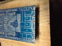
Okay, I think I had a elderly moment. I was reading between both rails and not center common. The center hole is the common, the two outer are the positive and the two second to the inside are the negative. With negative lead on my DMM on the center and positive on either outside holes reading is a (+146vdc). And still with the negative lead on the center and positive lead on the two either side inner reading is a (-145vdc). Before I was reading between the two on either side and not using the center common. Thanks Perry. Still have the issue with the amp side.
Attachments
Found that the two lm7812 transistors were bad replaced them. Replaced all the FDA24n40's , all 32. Replaced the four IR21844S. Powered up and checked voltage.
145 vdc on the positive rail
-145 vdc on the negative rail.
Have sound on the bench.
Left it on for over an hour at a low volume with no issues.
Installed it back in my vehicle powered back up to set the gain, ten seconds on with volume at "0" and the amp pops again.
I am still not sure why this keeps happening. Everything is within parameters. Battery voltage was at 12.8. Speakers are at 0.7 ohm.
I can't seem to find anything else that is wrong with it. Ideas?
This can happen when there is an intermittently shorted inductor or damaged vias for the driver board. If you push/pull/twist on the output filter inductors, it may reveal an intermittent problem.
How bad is the damage?
How bad is the damage?
It always blows the faces off the transistors. The FDA24n40's. Not all just usually one side or the other. Hasn't really blown all just a few. But I always have just replaced all. The only things I haven't replaced are the three ic's in the middle of the driver board. The op-amp and the comparator. Not sure what U6 is. The picture of the board is on a previous page. And as well I always change the four drivers 21844s.
It doesn't really damage the board, other than cause me to change everything.
It doesn't really damage the board, other than cause me to change everything.
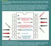
U6 is either an LM293 or LM393 (or equivalent). It's used for over-current protection.
I don't think the TL072 or the LM211 can cause the amp to fail (I could be wrong).
Previously, have you checked the various components on the main board (small inductors, 1 ohm resistors, transient surge protectors...) that connect to the driver board?
I don't think the TL072 or the LM211 can cause the amp to fail (I could be wrong).
Previously, have you checked the various components on the main board (small inductors, 1 ohm resistors, transient surge protectors...) that connect to the driver board?
I have. All checked out good. Is it possible that the initial ohm load is causing it to, for lack of better words, go into a high duty cycle without any input?
I know most of the history on this amp.
It was played on a 1/2 ohm load at a high supply voltage.
It was set up on a 14 volt battery system and was charged at 16+.
I know this model is unstable at 16 volts and higher. And it failed at a low volume not high volume where the supply voltage would be highest.
When I replaced the two 7812 I checked the supply for them which was 140 volts. That's too high from what I have read.
The 78 series regulators are limited to about 35v. There is a dedicated supply that drives about 25v to them.
I don't understand the question about the duty cycle. The output stage will be OK for all duty cycles from 0% to 100%.
Are you checking the driver ICs to confirm that none are being damaged when you soldered them onto the board? They are relatively fragile.
I don't understand the question about the duty cycle. The output stage will be OK for all duty cycles from 0% to 100%.
Are you checking the driver ICs to confirm that none are being damaged when you soldered them onto the board? They are relatively fragile.
Okay, I have seen some amps that had a issues on the output stage.
I am checking the driver IC's. My hands do shake and my eyes aren't what they used to be,but I am going back over my work.
I was concerned about removing the driver board so many times that I have installed sockets so its easily removed from the main board. This was so I could check drive signal to the outputs without them on the board. And then remove it and install the outputs and recheck. Probably sounds stupid or strange.
Single row sockets have a fair chance of having an intermittent connection. Any intermittent connection could cause the amp to fail. If they were removed from the amp before reinstalling it in the vehicle, that's not the problem.
I understand about the shaky hands. I was going to do some youtube videos but the shaky hands would have been too distracting. For close-up work, I stack +3 and +2.5 diopter reading glasses.
When you say that you checked the driver ICs, did you mean the solder connections or the resistance between pins? Checking the individual drive sections and comparing one to another can sometimes tell you if you damaged the IC when heating it.
Attachments
- Status
- Not open for further replies.
- Home
- General Interest
- Car Audio
- Crossfire xs8k