Thanks,
I updated the SB15 files in XSIM.
I think I traced that XT25 in FP Trace and made the FRD and ZMA files.
Attached is what I guess is my best X-over, but I'm kind of all confused due to the number of cross-overs I've made partially.
I updated the SB15 files in XSIM.
I think I traced that XT25 in FP Trace and made the FRD and ZMA files.
Attached is what I guess is my best X-over, but I'm kind of all confused
due to the number of cross-overs I've made partially.Attachments
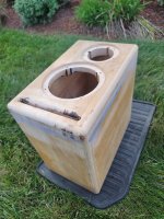
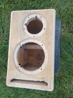
Can you please give me your baffle dimensions
driver placement on baffle - positions
box volume and tuning if vented?
driver placement on baffle - positions
box volume and tuning if vented?
Last edited:
You're helping me a ton, for some reasonPlease tell me your baffle dimensions and driver placement on baffle and also box volume (and tuning if vented). I can then apply your specific box and baffle diffraction which will give curves closer to reality than just using manufacturer data. I will upload both options so you can see the differences.

I did forget to give you the dimensions.
I was thinking that tweaking the cross-over in XSIM early today.
Should I redo the XT25 FRD and ZMA? I can't get the level right on the FRD files so I adjust "mod sensitivity" in XSIM.
But the SB15MCF FRD from the download you gave me seems to be spot on, although I really didn't check it that well.
The XT25 I had to adjust "mod sensitivity" in XSIM to "-5.5".
Be right back with the dimensions.
Thanks. The reason for the dimensions and enclosure details is they affect the frequency response. This will affect the phase response and therefore the crossover effectiveness. Your "in phase" crossover looks great now, but it will change (how much I don't know) once we get the FRD closer to what your box will do to the manufacturer curves. The manufacturer curves are done on an IEC (large) baffle, and they don't have the bass losses nor "ripple" caused by your speaker baffle and box.
Re FRD files - having matched sensitivity (SPL) is vital . I don't know what you mean by "level right on FRD files". As long as you trace graphs accurately, and both represent the same input (e.g. 2.83v) then the levels match.
It becomes a problem if the drivers are measured at a power level (and different impedance) and not same voltage (drive) level.
For mod sensitivity - I don't know what "-5.5" represents - is this distance (inch or mm) or time (msec)?
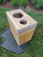
Outer dimensions -- 20.00 x 33.34 x 33.34 cm
Port is -- 15.6 x 1 x 27.3 cm -- 2 flared ends
Sides are 22 mm and front is 29.6 mm
Tweeter center is 7 cm from the top of the speaker and 12.7 mm off center.
Woofer is 20.32 cm from the top of the speaker.
The top of the SB15MFC30-08 woofer's dust-cap is 18 mm below the top of it's surround.
Inside dimensions not including the port -- 26.14 x 28.18 x 15.6 cm -- total volume 11.2 liters when done, I think
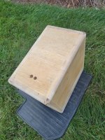
I didn't build the speakers correctly, due to all the misaligned grain. Sometimes it can hold though and not crack.
mod sensitivity brings the FR up or down in the XSIM Graph. So "-5.5" means I adjusted it 5.5 dB down in the XSIM graph. I THINK, that's all it does.
When tracing I can get the Y axis "stretch" correct after a few tries, but where the graph lands on the Y axis is very hard for me to predict.
Port is -- 15.6 x 1 x 27.3 cm -- 2 flared ends
Sides are 22 mm and front is 29.6 mm
Tweeter center is 7 cm from the top of the speaker and 12.7 mm off center.
Woofer is 20.32 cm from the top of the speaker.
The top of the SB15MFC30-08 woofer's dust-cap is 18 mm below the top of it's surround.
Inside dimensions not including the port -- 26.14 x 28.18 x 15.6 cm -- total volume 11.2 liters when done, I think
I didn't build the speakers correctly, due to all the misaligned grain. Sometimes it can hold though and not crack.
mod sensitivity brings the FR up or down in the XSIM Graph. So "-5.5" means I adjusted it 5.5 dB down in the XSIM graph. I THINK, that's all it does.
When tracing I can get the Y axis "stretch" correct after a few tries, but where the graph lands on the Y axis is very hard for me to predict.
Last edited:

I'm not sure you want to boost or subtract either drivers raw response. This is because they are both measured at 2.83v on an IEC baffle. That the tweeter is more sensitive than the woofer is perfectly normal and why we design a crossover to "pad down" the tweeter to the woofer's level.
We do need to estimate the woofer Z axis offset - that is distance the woofer dustcap is behind the tweeter dome. A measurement with a ruler is usually good enough from the centre of the woofer dustcap to where it would be flush with the baffle (i.e. basket frame front edge) assuming you are recessing drivers for a flush mount.
Thanks for the dimensions. I won't have time today, but will run them through a baffle sim tomorrow and upload. I'll also plug in your current crossover to both raw and "cooked" curves to show you the potential difference
I think the woofer's dust-cap is only 12mm behind the tweeter's ring radiator, maybe 13mm.
mod sensitivity brings the FR up or down in the XSIM Graph.
So "-5.5" means I adjusted it -5.5 dB down in the XSIM graph. I THINK, that's all it does.
This means instead of 93 dB the tweeter's FDR has a sensitivity of 98.5. From the FP trace I did it doesn't land on the x axis correctly.
I don't know why.
The SB15MFC trace I did needed a full +28 dB to get it's position on the X-axis (up and down) correctly.
The SB acoustics files you gave me seem to be spot on.
Attachments


I see - so you were adjusting SPL to make up for a tracing issue? All good. This won't affect phase / crossover, as long as you matched the drivers correctly (when lined up to manufacturer curves).
I'm in 2 minds about acoustic offset. I need to check some material. I am unsure if it should be dustcap centre, or as close to the dustcap / cone intersection which puts the voice coil offset slightly further back. Having said that, 3mm at a nominal 2,000Hz XO frequency is only a phase difference of ~6 degrees, so I don't think super critical (since this is all best guesses on simulated data anyway).
Nice enclosure BTW. looks solid.
Okay, so, turns out (and I kind of already knew this) I'm not that smart because on "FP Trace" where is states the X axis and Y axis scale, I did NOT adjust it to match what is in my graph's scale is and that's just silly.
Attached are the SB15MFC FRD and ZMA files you gave me and some new (accurate) XT25 FRD and ZMA files I just made.
SB15MFC30-08 "mod delay" is -0.5 inches (-12.7 mm) I will post x-over pics in a few minutes, but they look way better already, just by updating the XT25BG60 FRD and ZMA files.
Attached are the SB15MFC FRD and ZMA files you gave me and some new (accurate) XT25 FRD and ZMA files I just made.
SB15MFC30-08 "mod delay" is -0.5 inches (-12.7 mm) I will post x-over pics in a few minutes, but they look way better already, just by updating the XT25BG60 FRD and ZMA files.
Attachments
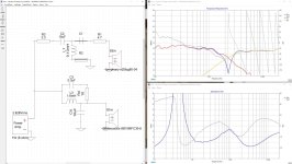
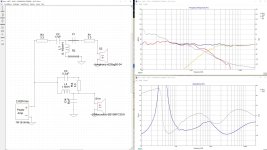
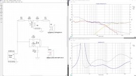
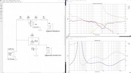
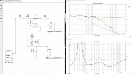
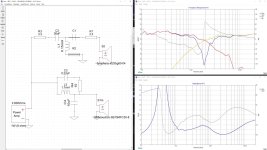
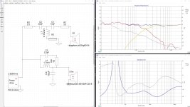
I don't know if these graphs look okay.
I could make C1 on the tweeter active, but I'm not sure I need to.
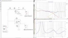
2 pics on the left are with C1 off and 2 pics on the right are with C1 on.
I could make C1 on the tweeter active, but I'm not sure I need to.
2 pics on the left are with C1 off and 2 pics on the right are with C1 on.
Attachments
-
 BEST -- SB XO -- SB15NRX30-8 XT25BG60 -- 09-27-23 --.jpg315.9 KB · Views: 100
 -
 BEST -- SB XO -- SB15NRX30-8 XT25BG60 -- 09-27-23 --2.jpg302.8 KB · Views: 79
 -
 BEST2 -- SB XO -- SB15NRX30-8 XT25BG60 -- 09-27-23 -- 2.jpg309.6 KB · Views: 71
 -
 BEST2 -- SB XO -- SB15NRX30-8 XT25BG60 -- 09-27-23 --.jpg313.7 KB · Views: 94
Last edited:
PS: Where are you going to place these speakers? Up against the wall or listen nearfield on your desk? or stuffed into a bookshelf?
The only remaining concerns I have is the XT25:
1. You are playing this higher in SPL low down compared to Zaph's http://zaphaudio.com/ZD5.html
2. Zaph strongly recommended an impedance notch to tame any ringing at resonance which he claimed was clearly audible.
The impedance circuit is pretty cheap / simple (using 19AWG inductor + resistor + electrolytic cap).
I'll model with / without it to see if it makes a measurable difference, however it is likely given Zaph's reputation to make an audible one.
I'll reread Zaph's 2-way reference speaker webpage.
I like this cross-over, but seems low.
I can also put 18 db electrical on the tweeter, but I don't get a nice reverse null, so don't know if it will be okay.
xt25bg60 is a little different than the 30
rolls off faster and has less low end distortion
I have 51 uf caps, 4 of them, but they are giant and I don't like the thought of electrolytics
I can do a 12 db x-over on the tweeter at 2.6 khz
IS that better?
I can also do a 18 db x-over at 2.6 khz on the tweeter, but I don't get a nice reverse null
Also it doesn't look like a 18 db attenuates the tweeter that much more than 12 db
In stead of being at 50 db at 500 Hz, it's 50 db at 540 Hz
Attachments
This guy's site is great. I should use his graphs next time.
https://hificompass.com/en/speakers/measurements/vifa/vifa-xt25tg30-04
https://hificompass.com/en/speakers/measurements/vifa/vifa-xt25bg60-04
https://hificompass.com/en/speakers/measurements/vifa/vifa-xt25tg30-04
https://hificompass.com/en/speakers/measurements/vifa/vifa-xt25bg60-04
Ok I think the first problem is your "mod offset". You've put this on the tweeter when we normally put this on the drivers with an acoustic centre further away from the tweeter. In this case the woofer.
You've pushed the tweeter back, when you should be pushing the woofer back (assuming your design / listening axis is tweeter level).
i.e. I can replicate your crossover with the wrong mod offset on the tweeter:

When I put the 12.7mm offset on the woofer, I get this:

I will apply your box / baffle response to raw measurements and see where we get to.
You've pushed the tweeter back, when you should be pushing the woofer back (assuming your design / listening axis is tweeter level).
i.e. I can replicate your crossover with the wrong mod offset on the tweeter:
When I put the 12.7mm offset on the woofer, I get this:
I will apply your box / baffle response to raw measurements and see where we get to.
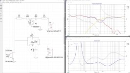
Here is your woofer sim.
DARK BLUE is the IEC baffle
GREEN is your baffle's effect on the driver response
LIGHT BLUE is the infinite baffle base response indicative of an IEC baffle measurement
YELLOW is your vented box response
PINK is the original manufacturer SB15MFC on axis FR measurement
WHITE is the corrected measurement of the driver in your box.

HEre is the tweeter:

There are no box responses applicable, since the tweeter is not affected by box (being a sealed unit) - only baffle, hence less curves. again DARK BLUE = IEC baffle and GREEN is your baffle
In both cases - you can see baffle step coming into play. That is the BLUE curve shows a "boost" between about 100 to 500Hz over your in box GREEN response. This is because there is more baffle, therefore 4pi to 2pi radiation occurs earlier (bigger baffle = longer wavelengths propagate forward = lower frequencies)
DARK BLUE is the IEC baffle
GREEN is your baffle's effect on the driver response
LIGHT BLUE is the infinite baffle base response indicative of an IEC baffle measurement
YELLOW is your vented box response
PINK is the original manufacturer SB15MFC on axis FR measurement
WHITE is the corrected measurement of the driver in your box.
HEre is the tweeter:
There are no box responses applicable, since the tweeter is not affected by box (being a sealed unit) - only baffle, hence less curves. again DARK BLUE = IEC baffle and GREEN is your baffle
In both cases - you can see baffle step coming into play. That is the BLUE curve shows a "boost" between about 100 to 500Hz over your in box GREEN response. This is because there is more baffle, therefore 4pi to 2pi radiation occurs earlier (bigger baffle = longer wavelengths propagate forward = lower frequencies)
I've reworked your crossover. I aimed for a 84dB nominal sensitivity (approx 3dB baffle step). This can be increased. I also added in the impedance flattening circuit used by Zaph to eliminate any unwanted noise from the XT25 at resonance:

Here's the reverse null:

Impedance is a healthy 6.2ohm minimum
If you want an option with more baffle step allowed for (i.e. lower sensitivity) or tweeter padding options, I can apply.
Here's the reverse null:
Impedance is a healthy 6.2ohm minimum
If you want an option with more baffle step allowed for (i.e. lower sensitivity) or tweeter padding options, I can apply.
- Home
- Loudspeakers
- Multi-Way
- Cross-over for -- VIFA XT25BG60-04 and SB Acoustics SB15MFC30-8