Hi,
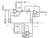
I've got some issue's with my preamp. The preamp is based on sallen-key topology. As you can see in the attachement, the opamps are single supply.
I used the tl064, the first en second opamp drive a high pass filter. The third and fourth are driving a low pass filter. Both preamps have variable resistors.
The problem is that the variable resistor from the low pass filter, has an influence on the high pass channel.
So turning the pot, results in frequency shifting on both channels.
Could this be the result, that one side of the variable resistor in the low pass channel is connected to the virtual ground?
Attachments
You didn't seriously draw this one in MS Paint, did you? 'cause it sure looks like it. There are better online schematic capture tools out there, just saying (not to mention the luxury of full-blown EDA software like KiCAD; even LTspice would work halfway well if you managed to download a potentiometer symbol) - unless, of course, this is your preferred way of inflicting pain upon yourself. 😉 Just look around for a bit.
The output impedance of a virtual ground buffer is never exactly zero, but the apparent extent of your problem suggests that there may be something more seriously amiss. Vgnd buffer not even working, miswiring, whatever.
This circuit strikes me as rather crude in general. Low input impedance, rather noisy, and I would have done the virtual grounding a bit differently. I guess your 12 V supply is a little wall wart that just feeds this preamp? Then you could have referenced any and all signal grounds to virtual ground. I.e. link virtual ground to your "real" ground, so your power supply effectively becomes +/-6 V. Doesn't matter one bit as long as the supply is floating, and it eliminates any potential disagreements about ground potential and extra noise.
What are you trying to do with this thing anyway? What does one need multiple outputs with independent lowpass and highpass filters for? I could imagine the need for a state-variable crossover for an active speaker setup, but this? Instrument (synth) use? Lab use?
The 10k on the input both before and after the cap is unnecessary - the one before the cap is just to discharge the cap before a new jack is plugged in, 1M or 100k is fine there.
Only the signal ground needs to be a star ground, the supplies negative rail doesn't need to be special if the virtual ground used for signals is the reference point.
Be consistent with signal ground - all signals refer to it, not just some, and it is the ground that needs to be a star-ground.
With lots of circuitry operating from the same virtual ground the opamp generating it needs to have enough current sourcing/sinking ability - this is why you'd normally use a dual supply for anything using more than a couple of opamps, no worry about overloading the virtual ground.
Hi,
Many thanks for the advice. Problem solved a broken cable was the culprit. @sgrossklass normally i use NI for drawing and then exporting. But i hadn't CAD available at the time.
I'm still expermenting with the basics of analog audio and indeed the input is noisy. So what do you advice as input filtering?