Yes...
With 45.xxx/49.xxx clocks, the clock divider should be set to 1:2, this provides the Amanero with the needed 1/2 rate clock signals.
Aa sorry no I meant the 45.xxx/49.xxx clocks. J1:2 is correct right?
I tried a jumper on MCK_SEL with no luck but I will put it back. I will check if and in what manner the signal reaches the buffalo.
With 45.xxx/49.xxx clocks, the clock divider should be set to 1:2, this provides the Amanero with the needed 1/2 rate clock signals.
Great !
Maybe it could be a good idea to start a specific thread, like the Hermes-Amanero one
Thanks for confirming!
For easy testing, should I see a data signal on the Amanero when not connected to Hermes/Cronus?
There only is 0V or 3.3V on the output pins of the Amanero on the scope, not a data signal. 🙄 I measured the same on the B3 side.
So yeah the Mac still recognises the Amanero and I can play music to it but there is no data signal.
Any ideas what to try next? I'm considering reflashing the Amanero.
Hi!Hi,
can anyone say if the Miero mod/update will work with ROPIEE,
which is what I run on the Rpie which outputs to an iancanada
The current package from miero can be used to build the overlay file on the last raspbian with 5.4 kernel.
(But not the recent Raspberry OS with 5.10 kernel)
If ropieee is still with a 5.4 kernel too, then you should be able to copy the tpa-hermes-rpi.dtbo file in the right folder and add this line to config.txt
dtoverlay=tpa-hermes-rpi
Now that the Hermes-RPi is a reality, pushing the code to the raspberry linux github repository would be simplier for everybody.
Sooo I resoldered all joints and reflashed the Amanero (with Slave_for_1080 and 1096c). Still no luck. I am getting a flat 3.3V on DCK and D1 0V on D2. I do see a clock signal on MCK but my scope only goes to 20 MHz so I can't be certain but I think it is OK. When I change to J1:1 I do see a signal on the outputs. Shouldn't I see a clock signal on the MCK of the Amanero? I'm not seeing it. I do see it when I remove the jumper from MCK_SEL but that doesn't change the output on the Cronus.
What else can this be? A power supply issue? I don't see a voltage dip, it stays at about 5.05 V.
I tried the Amanero with CPLD_for_1080, this gives a signal I would expect on the Amanero pins, a good clock signal on MCLK and data signals.
Will the Amanero work if I feed it with a clock directly from Cronus? Where can source the 1:2 clock? What can I measure to rule things out?
Note that with the Buffalo/Cronus you will need a 45.1584 clock on the Cronus to achieve DSD 256, and if you want to try DSD 512 you will need a 90.3168 clock.
Hi Barrows, why does Buffalo/Cronus need a 4 times higher clock than normally necessary for dsd256 playback?
Getting a little bit further 🙂 I now have a proper looking signal at the Cronus output.
I cannot find anywhere, what does a jumper on HMCK_SEL do?
Found out that the Amanero plays even when there is no master clock signal. I read somewhere this shouldn't happen. Also found out that you need to power on the Cronus, then plug the USB into the computer otherwise there will be no signal at the Cronus. (Even though the Amanero seems to be playing).
The issue is with the Cronus/Teleporter combination somehow. Can the input voltage for the Teleporter be too low?
Nope, input voltage wasn't too low. It was me not soldering the RJ connector to the board.. After 4 evenings testing I finally saw it haha.
I learned a few things along the way though which I hadn't otherwise.
I learned a few things along the way though which I hadn't otherwise.
No 3.3V at output from Cronus to Hermes
Hello everyone, can I ask for help?
I recently purchased Amanero / Hermes / Cronus Combo boards for Buffalo III DAC. Connecting Cronus to BIII is made directly via a 20pin header (so there is no mistake when connecting). I coped with the change Amanero to Slave firmware etc.
After all NO LOCK :-(
I checked Amanero connected directly to BIII via I2S, with CPLD_for_1080 and it works correctly.
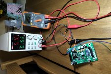
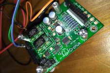
Then I checked the Cronos module and as you can see that when I give 5V power to the supply header of Cronus, I have not 3.3V voltage on the appropriate Cronus pins for the Hermes module.
Does this mean that the new arrived Cronus module is not working properly?
Hello everyone, can I ask for help?
I recently purchased Amanero / Hermes / Cronus Combo boards for Buffalo III DAC. Connecting Cronus to BIII is made directly via a 20pin header (so there is no mistake when connecting). I coped with the change Amanero to Slave firmware etc.
After all NO LOCK :-(
I checked Amanero connected directly to BIII via I2S, with CPLD_for_1080 and it works correctly.
Then I checked the Cronos module and as you can see that when I give 5V power to the supply header of Cronus, I have not 3.3V voltage on the appropriate Cronus pins for the Hermes module.
Does this mean that the new arrived Cronus module is not working properly?
Attachments
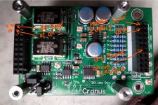
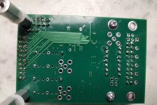
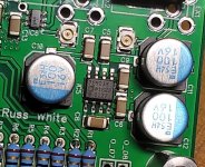
Incorrect Cronus v1.4 SMD soldering?
I am still looking at the received Cronus v1.4 module and please correct me if I am wrong, but is the ADM1750 linear regulator not mounted the other way around? This is suggested by other photos of the Cronus module on the internet. In addition, I checked it with a multimeter according to the datasheet https://docs.rs-online.c...98/0900766b812c18ef.pdf. Do you agree with me?
I am still looking at the received Cronus v1.4 module and please correct me if I am wrong, but is the ADM1750 linear regulator not mounted the other way around? This is suggested by other photos of the Cronus module on the internet. In addition, I checked it with a multimeter according to the datasheet https://docs.rs-online.c...98/0900766b812c18ef.pdf. Do you agree with me?
Attachments
That chip is definitely backwards, sorry about that. I will send you a replacement module.
Last edited:
Good morning, thank you for your answer. So I am waiting for a replacement Cronus module. Please check the new one before shipping.
Is it possible for me to buy Placid HD 2.1 Bipolar Power Supply Kit so that they are sent together since you are already sending the package to me? If so, how do I pay without shipping costs?
If you can, please attach one additional metal screw .. I lost one and these are screws with inch thread, which are not used in Europe.
Thank uou.
Brian, it is possible that the rotated AD 1750 chip burned out shortly after being first turned on. Do you think the Rhea modules survived this?
I have two suggestions,
1. If the problem is solder difficulty use Chip Quick to remove the connectors. It remains liquid long enough for the part to fall out.
2. With a little heat you can remove the pins from a male header to join the sockets.
1. If the problem is solder difficulty use Chip Quick to remove the connectors. It remains liquid long enough for the part to fall out.
2. With a little heat you can remove the pins from a male header to join the sockets.
I think Brian's suggestion is the safest.
The problem, really, is the size of the area that needs to be heated. One thing in your favor is the layout, which gives good access to the part. If you're a little bit brave, you can get rid of the black plastic part of the header, which will allow you to remove one through-hole component at a time using your soldering iron. I would go after it with a Dremel 1.5" cut-off disc, and cut parallel (and close) to the circuit board. Then you can clean up the board with solder-wick and flux, or a solder sucker, or a very small drill bit.
Good luck!
Thank you francolargo BrianDonegan pixelpusher
for the suggestions. 🙂
Brians sugg does sound safest.
I'll probably try the solder wick and sucker first, asper pixelpusher.
Failing that, cut, cut, cut.
Thanks again for the responses. 🙂
for the suggestions. 🙂
Brians sugg does sound safest.
I'll probably try the solder wick and sucker first, asper pixelpusher.
Failing that, cut, cut, cut.
Thanks again for the responses. 🙂
Hi Brian,
I wonder if you could share a design for a multiple clock output buffer? I am using some really nice external clocks into the chronus. I need multiple master clock and I2s outputs to drive dual mono DAC’s synchronously and an extra word clock to source an ADC. Ideally ufl or sma and at least a 3 way fan out. Laying out a true high frequency board is beyond my breadboarding skills so perhaps others might also wish for a little board or a bigger chronus? If you don’t have the time or think there is enough interest could you at least suggest a driver chip that you like? Thanks for the best digital I have yet experienced.
I wonder if you could share a design for a multiple clock output buffer? I am using some really nice external clocks into the chronus. I need multiple master clock and I2s outputs to drive dual mono DAC’s synchronously and an extra word clock to source an ADC. Ideally ufl or sma and at least a 3 way fan out. Laying out a true high frequency board is beyond my breadboarding skills so perhaps others might also wish for a little board or a bigger chronus? If you don’t have the time or think there is enough interest could you at least suggest a driver chip that you like? Thanks for the best digital I have yet experienced.
- Home
- More Vendors...
- Twisted Pear
- Cronus - It's about time.