I've been reading this treasure trove of soft-start info; Soft-Start Circuits
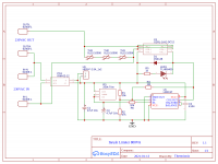
I'm using a 800VA Transformer (output 45-0-45V AC) with 22400uF caps, Input is fused before this board
250k trimpot gives ~0-2s delay adjustment till relay kicks in a removes inrush limiters from series with torroid primary.
The reset time should be quite low - need to measure once breadboarded
The inrush limiters should stay fairly cold - so should continue to provide protection on AC dropouts
They also won't catch fire compared to using wirewound resistors if the relay failed to kick in.
Resistance calcs for inrush limiting;
I = VA / V
I = 800 / 230 = 3.48A
R = V / (Ix2)
R = 230 / (3.48x2)
R = 33 Ohms
Primary parts;
https://mouser.com/ProductDetail/709-IRM02-12/
https://mouser.com/ProductDetail/653-G2RL-1A-E-DC12/
https://mouser.com/ProductDetail/995-SL15-10006/
LM311P Texas Instruments | Mouser
https://www.ti.com/lit/ds/symlink/lm311.pdf
I haven't played with a LM311 - datasheet says it can drive 50ma which will handle the relay coil fine
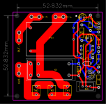
Any advice on layout improvements?
I'm using a 800VA Transformer (output 45-0-45V AC) with 22400uF caps, Input is fused before this board
250k trimpot gives ~0-2s delay adjustment till relay kicks in a removes inrush limiters from series with torroid primary.
The reset time should be quite low - need to measure once breadboarded
The inrush limiters should stay fairly cold - so should continue to provide protection on AC dropouts
They also won't catch fire compared to using wirewound resistors if the relay failed to kick in.
Resistance calcs for inrush limiting;
I = VA / V
I = 800 / 230 = 3.48A
R = V / (Ix2)
R = 230 / (3.48x2)
R = 33 Ohms
Primary parts;
https://mouser.com/ProductDetail/709-IRM02-12/
https://mouser.com/ProductDetail/653-G2RL-1A-E-DC12/
https://mouser.com/ProductDetail/995-SL15-10006/
LM311P Texas Instruments | Mouser
https://www.ti.com/lit/ds/symlink/lm311.pdf
I haven't played with a LM311 - datasheet says it can drive 50ma which will handle the relay coil fine
Any advice on layout improvements?
Attachments
Worth checking for arcing contacts and check the time it takes for the relay to close/open.
Tom has a nice article: The Ultimate Guide to Soft Start Design – Neurochrome
Tom has a nice article: The Ultimate Guide to Soft Start Design – Neurochrome
Diode in parallel with 250K trimpot, to quickly discharge C2 at shutdown (and be ready for a "hot restart" if it happens)
Changed meanwell to IRM-03-12 with 3W output (Planning to drive a 1W fan off the 12V jumpers)
Added D2 to drain C2
Added D2 to drain C2
It takes a few seconds for the Mean Well IRM-series to start up, so you may not need the delay circuit. Just have the Mean Well drive the relay directly. You generally only need a few mains cycles of soft start delay. The fan and the relay coil will ensure that the Mean Well discharges pretty quickly when the power is removed.
I suggest building a $10 current probe so you can measure the inrush current and check your work. I also suggest measuring the inrush current of the transformer before you commit to the inrush limiter NTC. I go through the steps here: The Ultimate Guide to Soft Start Design – Neurochrome
Make sure you have enough creepage distance between the high-voltage and low-voltage sides of the circuit. You need 6.35 mm (0.25") between mains and low voltage for Class II electrical safety.
Tom
Last edited:
Soft start - I'm thoroughly convinced now that the best soft start circuit is one that doesn't connects the AC power until the AC line crosses the zero point.
I've been repairing/refurbishing a commercial 800 watt class A/B audio amp with a 40lb transformer that develops +/-80v rails. It had some catastrophic event that took out most of the top side transistors as well as a half dozen components earlier in the chain. Anyway, This amp uses a triac module to deliver line voltage controlled at a lower current by the main power switch. The power switch closes and supplies the gate of the triac with enough voltage to turn it on. Triacs don't turn on until the V crosses zero. Voila!, instead of shocking your system with an almost infinite DV/DT at the peak of the cycle, the transformer gets connected to the line when it's close to zero volts. The event had taken out the triac BTW such that it went short circuit so the effect was, when you closed the power switch it didn't matter where in the ac cycle the transformer got connected. Under this circumstance the overhead lights in my lab would blink! After replacing the triac the lights no longer blink.
The circuit is simple, ie the power switch delivers AC to the gate via a 25ohm 1/2w resistor. The switch also directly connects to one of the triac anode/cathodes. The other anode/cathode connects to the transformer. So the triac also allows the use of a smaller power switch since it will never connect at the peak.
It's a very cheap soft start.
I have to thank forumer Indianajo. He recommend I buy the following current offering:
STMicroelectronics BTA40-800B
Digikey 497-2405-5-ND
$11.38
Attachments
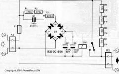
Here's the schematic. Note the components just after the power switch.
I have a bench sander that often starts with a jolt but some times it doesn't because I've hit the manual switch at the zero crossing. The jolt is bad! - big inertial load on the motor, ie the sanding disk. It often jars loose the disk securing screw. I plan to add one of these triacs.
I have a bench sander that often starts with a jolt but some times it doesn't because I've hit the manual switch at the zero crossing. The jolt is bad! - big inertial load on the motor, ie the sanding disk. It often jars loose the disk securing screw. I plan to add one of these triacs.
Attachments
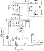
Here's the schematic. Note the components just after the power switch.
I may have read it all wrong, but that triac seems to be triggered to conduct anywhere in a cycle but +/-1.5V about zero crossing, at the moment the power switch closes the gate circuit.
It seems to me the purpose of using a triac is all for the longevity of the power switch by subjecting its contact to nothing more than a small gate triggering current. That circuit, on the other hand, does have the benefit of turning off at load current zero crossing when the power switch opens the gate circuit.
Please correct me if I missed it.
Well unfortunately the magnetizing current is 90° off the voltage and highest when there is a 0-crossing.
It is also that swiching on, the Xformer can saturate and create additionally a considerable current spike in the primary only limited by the DC resistance.
This happens also without load because the inrush current is double when the core is not magnetized.
The magnetizing current is then constant, flowing back and forth 90° and superimposed to the load current.
Great observation, Bansuri. I'm sure our thread starter, @Thermionix, is well aware that switching at the zero crossing is the worst case (maximum inrush current) condition. He says he's thoroughly studied the inrush page on Rod Elliott's website, and even gives a link to that page. Where Rod Elliott says:
Indeed 19 amps is a lot more than 4.4 amps. (bold italic emphasis added by me)
The above is an oscilloscope capture ... when power is applied at the zero crossing of the mains waveform. This is the worst case, and can result in an initial current spike that is limited only by the winding and mains wiring resistance. ... the peak reading of 1.9V represents 19 amps.
[instead,] if the mains is applied at the peak of the AC waveform, the peak inrush current for the same transformer is typically reduced to less than 1/4 of the worst case value ... 4.4A
Indeed 19 amps is a lot more than 4.4 amps. (bold italic emphasis added by me)
My lights used to dim when the amp was turned on with a shorted triac. They no longer dim with a functional one.
I have all the respect in the World for ESP but notice in that article he gave the zero crossing example but offered no peak crossing example - just a statement. I think there may be other factors so I will repeat Rod's experiment and post it here.
I have all the respect in the World for ESP but notice in that article he gave the zero crossing example but offered no peak crossing example - just a statement. I think there may be other factors so I will repeat Rod's experiment and post it here.
So the old circuits with no triac but simply a thermistor (or resistor) that is shorted after a while with relay contacts still is the better choice it seems.
Just use this, works great and no maths even needed !😀
Jan,
Thanks for this simple delay. Could you repost a “clean” schematic if available, please. I can’t read some of the numbers, especially R3. looks like 220 Ohm. If so what is R3’s purpose with 2x470k in series? Also, a resistor in parallel with the relay coil would “reset” the delay by discharging C2 and C3?
Last edited:
Francois,
Hope this is better. This is not my circuit, I got it from the net and has used it a couple of times, works great !
Hope this is better. This is not my circuit, I got it from the net and has used it a couple of times, works great !
Attachments
Last edited:
C1 and C2 will discharge via the relay. At 50 or 60 Hz, the impedance of the 330 nF cap is much lower than the two 470kOhm resistors - it is about 10kOhms.
Looking for a non-soul sucking, err I mean power sucking, inrush limiter.
Bypass works but I find that you need to tune the capacitance and the time to bypass correctly or you catch a inrush jolt if the cap hasn't finished charging for any reason.
Resistors work but once bypassed they offer no protection.
A PNP-NPN current limiter works in LTSpice, and it keeps the inrush to a configured current, even if the system restarts or there's a dip in the power. That to me means it then protects the transformer secondary and the voltage regulator. Only issue is ltspice predicting a 30W dissipation during normal operation.
I'm thinking a NTC to take the short transformer inrush with a bypass on the mains side. Possibly with a MOV for any unexpected transients.
Last edited:
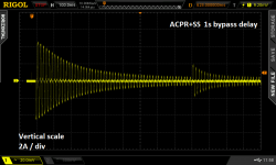
Several "soft start" PCB designs here on diyAudio, include a user selectable delay-before-bypass. Usually the options are 0.5 sec, 1.0 sec, 2.0 sec ; and usually they are chosen with pin jumpers (which are cheaper and physically smaller than DIP switches). Here's an example of a soft start circuit in action, feeding a stereo LM3886 chipamp whose power supply is the stock, standard diyAudio Universal PSU board, plus a 300VA Antek toroidal transformer ("AS3222").
AC mains current is limited to a peak inrush value of 4.5 amperes: two and a quarter vertical divisions on the scope. Then the (current limited) transformer + rectifier circuit sloooowly charges up the PSU filter capacitors. Finally, bypass mode shorts out the current limiter after 1 second. At the instant when bypass is enabled, mains current jumps, slightly, but is still comfortably below the inrush peak.
Naturally you get an even more benign transient when you select the bypass delay option to be 2 seconds instead of 1 second.
_
Attachments
Francois,
Hope this is better. This is not my circuit, I got it from the net and has used it a couple of times, works great !
I've built something similar a long time ago. I now tried to simulate the circuit and you might have to change C1 depending on the relay coil resistance (or rather switch-on current). In my particular example I have a relay with 77 ohm and 12V coil. So say we need about 150mA nominal current for the relay. I had to change C1 to 2.5uF (that's quite big for a 250V cap). Then the relay turns on in about 0.1ms. For 0.2ms delay you need already 2mF capacitance in total (for C2 and C3). Not a very flexible circuit, or did I miss something?
Edit. The circuit seems to work as is with a 1k relay and has then about 1s delay (according to my simulation).
Last edited:
- Home
- Amplifiers
- Power Supplies
- Critique my soft start