I want to learn more about electronics and the inner workings of audio equipment, so I've been modelling schematics I find online in KiCad.
I have need of a zero-gain buffer, so I've been reading up on preamps and buffer circuits, and have decided I want to build a opamp based buffer first. Something I can build on perfboard.
After that I'd like to move on to designing a PCB for a transistor based buffer like the Nelson Pass B1, but with regulated power supply and maybe some other features.
However I am an absolute noob when it comes to the theoretic side of electronics.
I was wondering if I could get some opinions on these schematics and if I'm heading in the right direction or not.
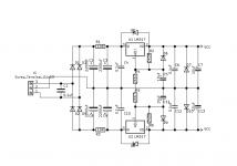
Is this power supply schematic somewhat overkill for a simple NE5532 buffer?
Any feedback would be greatly appreciated.
I have need of a zero-gain buffer, so I've been reading up on preamps and buffer circuits, and have decided I want to build a opamp based buffer first. Something I can build on perfboard.
After that I'd like to move on to designing a PCB for a transistor based buffer like the Nelson Pass B1, but with regulated power supply and maybe some other features.
However I am an absolute noob when it comes to the theoretic side of electronics.
I was wondering if I could get some opinions on these schematics and if I'm heading in the right direction or not.
Is this power supply schematic somewhat overkill for a simple NE5532 buffer?
Any feedback would be greatly appreciated.
Attachments
Everything looks okay. However, that's not a true zero-gain circuit, it actually has a gain of 1.1. If you haven't already seen it, Rod Elliott's site has a wealth of incredibly useful information - I can't recommend it highly enough. Have a look at this page of his: Audio Designs With Opamps . There's a section on buffers.
As for the power supply, in my experience there's no such thing as overkill 😉. A good power supply will bring out the best in any circuit. Plus if you build that PSU on a seperate perfboard you can use it for subsequent, more demanding projects.
On a more technical note, keep in mind not all op amps are unity gain stable, but you'll be okay with the NE5532. It might be a good idea to add a compensation cap depending on who the manufacturer is. Texas Instruments specify that theirs is internally compensated, but I don't know if other brands are.
I'd agree its basically OK as well.
Thoughts...
Maybe a bit of overkill on the PSU considering a few milliamps current draw. You could go much simpler with a simple Zener shunt stabilised supply using just a Zener and resistor per rail and do away with the regs.
I would AC couple the output. The 5532 is one of the worst (relatively speaking) for having high input bias currents which translate to noticeable offsets unless you deliberately design for DC precision. Do away with R4 and link out R7.
Is your power supply supposed to be a dual rail +- with virtual earth using two LM317's? If so then you cannot do it with a single bridge and center tapped transformer. For that you will need to use an LM317 and an LM337.
If you want to do dual rail with two LM317's you need to use a dual secondary transformer and a separate bridge for each leg.
Tony.
If you want to do dual rail with two LM317's you need to use a dual secondary transformer and a separate bridge for each leg.
Tony.
Actually wintermutes thoughts have shown up another anomaly which is D8 which looks to be reversed.
Actually wintermutes thoughts have shown up another anomaly which is D8 which looks to be reversed.
Scrub that... the negative side is all wrong 🙂 It's a copy of the upper sections... so that won't work.

Yes 337 in the negative side should fix things 😉 It is possible to use two 317's but as I said you have to use a dual secondary transformer and also dual bridges and quite a bit of modification to that circuit.
Tony.
Tony.
Everything looks okay. However, that's not a true zero-gain circuit, it actually has a gain of 1.1. If you haven't already seen it, Rod Elliott's site has a wealth of incredibly useful information - I can't recommend it highly enough. Have a look at this page of his: Audio Designs With Opamps . There's a section on buffers.
As for the power supply, in my experience there's no such thing as overkill 😉. A good power supply will bring out the best in any circuit. Plus if you build that PSU on a seperate perfboard you can use it for subsequent, more demanding projects.
On a more technical note, keep in mind not all op amps are unity gain stable, but you'll be okay with the NE5532. It might be a good idea to add a compensation cap depending on who the manufacturer is. Texas Instruments specify that theirs is internally compensated, but I don't know if other brands are.
Yes, that website is a wealth of information indeed. I learned a lot from that website in the last 48 hours or so 🙂
I could build it on a seperate board, but there are plenty of LM317 regulated supply modules available on ebay and such for just a few bucks. Seems like a waste to recreate something similar. My goal is to prototype it so I can eventually adapt and integrate it into other designs. For instance a single rail version that spits out 18 clean VDC to power the Nelson Pass B1 buffer.
I'd agree its basically OK as well.
I would AC couple the output. The 5532 is one of the worst (relatively speaking) for having high input bias currents which translate to noticeable offsets unless you deliberately design for DC precision. Do away with R4 and link out R7.
I would prefer to take out the gain resistors and have it as a true unity gain buffer. I had just assumed there might be some benefit to these resistors. That's why I put them in and choose the values to be close to unity gain.
I guess I'll use a center tapped transformer, but I want to make this schematic as universal as possible.Is your power supply supposed to be a dual rail +- with virtual earth using two LM317's? If so then you cannot do it with a single bridge and center tapped transformer. For that you will need to use an LM317 and an LM337.
If you want to do dual rail with two LM317's you need to use a dual secondary transformer and a separate bridge for each leg.
Tony.
So if I understand correctly when I use 2 of the same regulators with a shared ground not connected to a transformer, I'd just get 2 positive power outputs?
So the LM317 regulates positive DC where as LM337 regulates negative DC?
The supply 😉
Mona
Thanks! My mistakes where obvious.
I guess I'll use a center tapped transformer, but I want to make this schematic as universal as possible.
Remember to connect the audio ground to the power supply ground.
Unless you are using the premium LM 317/337 parts, R2/6 should ideally be 120R instead of 240R. It has to do with the minimum load current required to maintain regulation. In some instances, it won't matter if there is a minimum load >= 10 mA. It is a good practice to use 120 R with the standard spec parts as a rule.
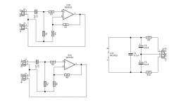
Another question I have is about frequency compensation. I know that the NE5532 has an internal capacitor to do this so it's not necessary. But if I were to use an opamp without internal compensation in unity gain, like the single channel NE5534, it is required to add a 22pF cap externally. I have digged through webpage after webpage, but have not found a definitive answer as to WHERE this compensation capacitor should be placed.
My best guess is this, could someone validate that for me?
Top diagram in non-inverting, and bottom in inverting configuration
My best guess is this, could someone validate that for me?
Top diagram in non-inverting, and bottom in inverting configuration
Attachments

The 5534 is a single opamp and brings into use two of the extra pins, pins 5 and 8.
For a unity gain buffer with the 5532 it is not needed and in fact can even be applied without altering the circuit somewhat. The standard buffer configuration requires the direct connection between inverting input and the output.
I wouldn't really advise the 5534 for a buffer, use the 5532 instead.
Your inverting configuration with the 1k's is OK but remember the 1k sets the input impedance. So it is very low.
Attachments
You forgot to turn around D10!The supply 😉
Mona
Also to the OP, note that the pinout of the LM337 is different from LM317, as correctly labeled in Ketje's schematic. It's yet another gotcha with positive and negative regulators. Don't rely on what makes sense or "how it should be," read the data sheet and READ IT AGAIN!
Oops, you are right, forget oneYou forgot to turn around D10!

With two same regulators it can be done but competely separated.So if I understand correctly when I use 2 of the same regulators with a shared ground not connected to a transformer, I'd just get 2 positive power outputs?
Mona
Attachments

The 5534 is a single opamp and brings into use two of the extra pins, pins 5 and 8.
For a unity gain buffer with the 5532 it is not needed and in fact can even be applied without altering the circuit somewhat. The standard buffer configuration requires the direct connection between inverting input and the output.
I wouldn't really advise the 5534 for a buffer, use the 5532 instead.
Your inverting configuration with the 1k's is OK but remember the 1k sets the input impedance. So it is very low.
Yes I'm aware the single channel makes little sense to use as in a (stereo) buffer. However at this point I'm just trying to learn about opamps and preamplifiers.
I do plan to make a signal inverter to use on one of the channels of my L25D amplifier. I thought NE5534 or TL071 could be possible options.
I hear it can help against bus pumping to invert one of the channels at the input. Not that I really encountered this problem, but it is yet again a budget friendly and educational little project for me to get more familiar with the theoretic side of electronics. So far I've only build pcb kits, and I feel there is much more to learn when I actually model schematics and then design a pcb or build them on perfboard.
Well... I would definitely urge you to try the TL071 and TL072 (dual opamp). These are FET input devices and suffer no DC offset like can occur with the 5532.
If you try an inverting stage then just keep in mind the input impedance is determined by that first 'input' resistor. 10k is a pretty good compromise and can be driven from any solid state gear.
Have you looked at how to calculate gain and why it actually works as it does?
If you remember the golden rule of "the output will do whatever is needed to keep the difference between the two inputs at zero" then it will all make a bit more sense.
Opamps are fun 🙂
Right, Vin ( + to - ) is zero and Iin is zero simplifies everything. As far as the power supply goes, if you add a couple of pots you can make it adjustable and use it as a lab supply.
I hear it can help against bus pumping to invert one of the channels at the input. Not that I really encountered this problem
??? Never heard of bus pumping unless theres compressors involved. And even if it did exist, swapping phase of one channel is never good, it will destroy the stereo image and reduce the bass.
??? Never heard of bus pumping unless theres compressors involved. And even if it did exist, swapping phase of one channel is never good, it will destroy the stereo image and reduce the bass.
Switching the output wires after amplification should compensate for the phase shift.
I read it here
L20D Class D amplifier | Mayday DIY audio
There's also some discussion on the topic in this thread.
Bus Pumping with 3 or more amps on a single supply
I'm honestly not even sure if it is a real thing or not...
- Home
- Source & Line
- Analog Line Level
- Criticize my schematic