I picked up 3off Crimson FET 2.5 modules on eBay very cheaply and i would like to get them tested/working. Does anyone have a schematic they can share or know the operating specifications for this module? They seem to be a bit of a rarity and not nearly as well-known as the Crimson Elektrik bipolar transistor amp modules. I know Brian Powell has been very helpful in the past and he may have posted these already?. This is not a complicated board so would be fairly easy to trace out the design but it would be helpful to get any information about them from anyone who knows or has a working amplifier already 🙂
Attachments
I remember the first modules being advertised for sale along with another company in the UK with claims for wattage's of 100,s of watts .
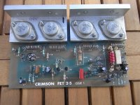
The ones you have relate to the late 1970,s/1980,s and I have used those same mosfets in several mosfet amplifiers ---VERY reliable ! - good quality ( original manufacturer ) nice sound---don't sell them .
It looks original with authentic passive components of that era.
Crimson ready built amplifiers were well thought of by UK "golden ears " like Alvin Gold etc.
As they were kits before they were integrated into boxes you would need to find somebody who bought a kit as I don't think there is a commercial schematic with exactly the same circuit .
But -as you say --very simple to trace out --no big deal.
If you do it right adding a front end to them will give you good quality audio ,change C10 though I recognize it and the capacitor type in the zobal network if it is not polycarbonate/polypropylene .
Get it working first before thinking of changing anything else .
Hi Duncan2, thanks for the extra useful info. I think there may also have been a later version called FET 3.0? I already have a lot of Crimson amplifier kit/modules and re-built a CK1100 amplifier a few years ago which sounds really good, so hoping for similar results with the FET 2.5 modules. I hope the FET's are all functional because, as you say, they are originals and replacements will be rare as hens teeth (and expensive!). I will see if anyone else has the original technical specifications and schematics before i attempt to trace out the schematic. At least there will be a copy available for anyone else who may be in the same situation ;-)
A quick eyeball suggests it's yet another version of that classic circuit from the original Hitachi MOSFET app notes.
Knowing that, the tracing will go VERY quickly.
🙂
mlloyd1
Knowing that, the tracing will go VERY quickly.
🙂
mlloyd1
Thanks mlloyd1, i thought i recognised that Maplin MOSFET design by the hand of Dave Goodman. Forget about tracing, just go to the link here:
A Paul Kemble web page - compact PA designs (2).
A Paul Kemble web page - compact PA designs (2).
Happy to report all 3 Crimson FET 2.5 modules are working, albeit I had to repair a broken track on one module which gave an output DC offset of 870mV, instead of the expected 50 - 60mV. There are several component value changes on the FET 2.5 modules compared to the standard Maplin Mosfet amp (not surprisingly 🙂) but the design is almost identical, apart from the addition of a gate-source 12V zener clamp circuit on the FET 2.5 mosfets. Also, the upper frequency response limit seems to be set about 4 times higher at around 160KHz due to the 2K2 input stage resistor changed to 560R. Probably time to get my soldering iron hot and build another amp 😉
- Home
- Amplifiers
- Solid State
- Crimson FET 2.5 Issue 1 Module Schematics