It should probabaly be mentioned that only the ground terminal on the PCB leading to the optocoupler should be points 2-3 (Rudy´s PSU schematic).
All others are connected to the "real" ground.
Cause these "grounds" are lead separately on the PCB you won´t short points2-3 to real ground.
Jens
All others are connected to the "real" ground.
Cause these "grounds" are lead separately on the PCB you won´t short points2-3 to real ground.
Jens
Hello Everybody,
Maybe this should have been another thread by itself but since we are talking about the Crescendo here I wanted to mention an
amp published in Elektor's july/august issue in 1983.Namely circuit number 78, the '40 Watt Main Amplifier',which was described as an alternative to Crescendo, for those who needed less power.I have built this one with a few modifications,RC filtering on supply rails,RC filtering on zener references,plastic power transistors and emitter resistors on the input differential pairs.(Afterall, what fun is amplifier building if you don't tweak the circuit in your own way).This is one of the quitest amps I have ever listened and I think sounds good too.For anyone wanting to experiment with output triples, I think this amp is a good example.At those times, output triples were regarded highly and if I remember correctly, QUAD and Crimson Elektrik used them in their amps.
The whole thing (2 channels + power supply + heatsink adapters)
fits on a PCB 18 cm. by 9 cm.If anybody is interested, I can post a picture.
Happy soldering

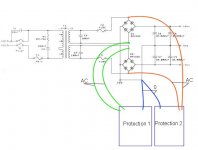
The power to the optocoupler will only be half-wave rectified if you do like that. The wires to the lower bridge serve no function and will never carry any current. I think you should connect both protection circuits to the upper bridge.
You could also parallel the green ones with the orange.
As long as the phase is right (as it obviuosly is now) it´ll work.
Ground is connected right as well.
How did you set up bias now and more important how does it sound?
Cheers
Jens
As long as the phase is right (as it obviuosly is now) it´ll work.
Ground is connected right as well.
How did you set up bias now and more important how does it sound?
Cheers
Jens
Megajocke
Is there any disadvantes if I connect both protection circuit to same bridge?
Is that then totally seperated mono amps any more? No I guess.
And other rail (other secondary winding) have more load than other? Any disadvantages or any hearable (sonic) difference?
Joensd
I know that I can connect those protection circuit parraller but it will be easier to connect at the moment like in my picture (post #24). So, can I connect like that?
Bias is set maximum what Elektor advise. I do not have listen it yet, only mono testing done 🙂
I thought you were using only one transformer.Is that then totally seperated mono amps any more? No I guess.

So how can you go "mono"?
And still: connecting the protection to only one bridge will not give you what you want: A check if both rails are "operating".
Jens
well, we do not have to make a big deal of it, just connect it like it works, the main reason for this circuit is for the the quick falloff when you release the power button, it alsow checks the voltage rails like joensd sad, but if there would be something wrong with the voltage rails the DC protection would be activated also, sow now problem at connecting them on 1 bridge only.
Btw, you can crank the bias-current up to about 800mA with some oversized heatsinks.
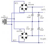
Little note i want to make, using double diodebridges means more chances on oscilation with this kind of amps. Just like some other elektor amps IGBT/HEXFET/original Crescendo they are already very sensitive when it comes to oscilation. And something else, if u use 2SK1530 and 2SJ201 you wil get about 90W, when using 2SK1530Y the power drops to about <80W, the sad thing is, i never found the original 2SK1530, not that i botter about the 10W
Greetz Rudy
Btw, you can crank the bias-current up to about 800mA with some oversized heatsinks.
Little note i want to make, using double diodebridges means more chances on oscilation with this kind of amps. Just like some other elektor amps IGBT/HEXFET/original Crescendo they are already very sensitive when it comes to oscilation. And something else, if u use 2SK1530 and 2SJ201 you wil get about 90W, when using 2SK1530Y the power drops to about <80W, the sad thing is, i never found the original 2SK1530, not that i botter about the 10W
Greetz Rudy
Joensd
Yes, one transformer, but I try say that will that cause any effects to channels crosstalk if I connect both protection circuit to same bridge? Or will this cause some effects to other rail? Or something, I don't know either what I meant that, because I write that last night when I was very tired 🙁
Rudy
But can I connect those protection circuit like I descripted on post #24. Because it's so easy connect those like that at the moment
-> all connectors are ready.
Yes I know that bias can be set up quite high, but because I have small heatsinks (smaller than Elektor advise) I don't do that.
How double rectifier bridge can raise risk to oscillation? Earlier on this page, almost everybody advised me to use two rectifier bridge againts one?
You´d theoretically have the crosstalk anyway cause of one transformer used. It has nothing to do with connecting the protection to one of the rails as you need two rails for each amplifier. So only two transformers would completely separate.Yes, one transformer, but I try say that will that cause any effects to channels crosstalk if I connect both protection circuit to same bridge? Or will this cause some effects to other rail? Or something, I don't know either what I meant that, because I write that last night when I was very tired
As the Crescendo has good PSRR I don´t think it matters.
And isn´t power supply crosstalk a specific kind of crossfeed?😉
Rudy, I ordered the 2SK1530 at Nedis if you wanna have 10W more.
Jens
How double rectifier bridge can raise risk to oscillation? Earlier on this page, almost everybody advised me to use two rectifier bridge againts one?
-> soundwise 2 bridges is better
maybe first explain why the use of 2 bridges
* when using 1 bridge and using a not so good starpoint, when current begins to flow there wil be a pottential diffirence between the point where the 2 trafo windings come together and the point where your inputsignal and outputsignal is connected due the current in the groundplane ( from the outputsignal that is ).
This means that the signal/noise ratio will be bad.
* Also when using 1 bridge the wiring of the transformer wil be pikking up some signal, see it like an antenna, and the wiring off in the transformer could get pretty large ...
but ... ( always the but ... )
* using 2 bridges means u use 2 diodes in series with the voltage rails, now the problem with diodes is that they have a voltage drop off about 0.6V ( min ) and the higher the voltagedrop the higher the currentpulse ( witch is HF noise ) will be when going from non-conducting to conducting. Sow using 2 diodes in series means more then the double off the currentpulse an a lot more HF noise on the rails, with some nice CRC filtering a lot off this could be removed, and adding some low value high power resistor in series with the AC windings from the transformer alsow helps a LOT.
The thing is when this noise is above normal values the amp begins to oscilate, where the amp has a rather nice PSRR on the low region it has a very bad PSRR on the higher frequentie regions.
Maybe a suggestion to make the confusion completely, why not use 2 bridges, but 1 for every channel and use seperated buffer-caps, sow that left and right are totally seperated except for the transformer. You will have a pretty nice channelseperation this way.
Little suggestion on the amp hitself, place a 100nF and a 1nF cap over C6 and C7, this makes that the amp will have a better PSRR.
And try to leave the servo out of the circuit, put a trimpotmeter at the bias pin and connect both supply voltages at it ( use 100K or something as the pot ), this only when you actually can stabilize the DC voltage at the output, the amp doesnt always allows this. It does sound a lot more ... lets say musical / clear after this modification ('s).
Have fun listening / building your amp
Greetz Rudy
Did you Rudy mean using two rectifiers ( one for every channel) that rectifiers are connected parralel?
Will that be better what you propsed, if I put those 100nF over C8 and C9. Close to amplifier circuits?
Now I have four 1yF polypropylene caps over big capasitors which are near amplifier circuits (two 10000yF for one amplifier circuit) . I have also main capasitors near rectifier bridges (four 10000yF).
Also I have 100nF caps over each diode on rectifier bridges!
I don't understand what you mean about And try to leave the servo out of the circuit
Attachments
Eccu
With the bridges i mean like in the picture below
The servo = R24,D5,D6,C6, IC1, R25
when leaving this components out of your PCB you have to add a potentiometer the adjust the DC output setting yourself, this circuit does this fully automaticly, but you can try this without removing to Servo circuit, just dont connect servo into the amplifier PCB but connect a potmeter to this pin. To try this, leave the amp on untill it reaches max temperature, set DC ouput to 0V ( so close possibel ) and then turn him off, wait untill the amp is cold ( about 2 hours ) and put him back on, if the DC voltage on the output is higher then 100mV the first minutes, then better use the servo system.
Greetz Rudy
Attachments
Thanks Rudy for advise, but I think I just finish this Crescendo like Elektor way. Because I have other projects on going at the moment.
Now both channels works... thanks to you Rudy and Joensd (and others). 😉
But now I have other problems
"Brum" or how should be call that about 50 Hz (or 100) noise from speakers.
Nothing connected to inputs and same noise still hearable from speakers (both channel).
I disconnect socket earth but still same noise🤐
That noise is not loud but hearable near speakers.
Can my wirings cause this if AC-lines are near DC-lines?
Or can there be some kind oscillation?
Transformer is placed to own different section in case and wall separates it from amplifiers circuits.
What should I do next?
Is there any thread about this? Which keywords for search?
I used Elektor´s PCB´s and they run the ground from PCB to speaker. If you did it similar connect speaker ground directly between the caps or your star ground.
Jens
Jens
joensd said:I used Elektor´s PCB´s and they run the ground from PCB to speaker. If you did it similar connect speaker ground directly between the caps or your star ground.
Jens
You mean that ground is same as zero (main capasitors center plate), I guess?
I try connect speaker (-) to main capasitors center (zero point) and speaker (+) directly to amplifier board but that "brum" is still hearable.
But if I disconnect AC power from switch, that "brum" fade out and sound is very clear (main capasitors still have charge (power) to drive amplifier).
Also I tried move transformer further distance from main capasitor and all wirings but still that damn "brum" coming out from my speakers.
Eccu said:
I try connect speaker (-) to main capasitors center (zero point) and speaker (+) directly to amplifier board but that "brum" is still hearable.
But if I disconnect AC power from switch, that "brum" fade out and sound is very clear (main capasitors still have charge (power) to drive amplifier).
Also I tried move transformer further distance from main capasitor and all wirings but still that damn "brum" coming out from my speakers.
Five things:
1) Have you connected the transformer's secondary earth to the star point?
2) Have you connected the star to the chassis you are using?
3) The ideal star point is not between the capacitors, but a little bit away from that point. About 1" would be fine.
4) Disconnect the AC ground wire from the star or the chassis and see if the hum goes away.
5) The speaker (-) should always be connected to the star. The protection ground should go to the star too, except if you are using a bridge arrangement, where the speaker (-) should float from the ground.
You should also check where your input earth is conected to.
Carlos
carlmart said:
Five things:
1) Have you connected the transformer's secondary earth to the star point?
2) Have you connected the star to the chassis you are using?
3) The ideal star point is not between the capacitors, but a little bit away from that point. About 1" would be fine.
4) Disconnect the AC ground wire from the star or the chassis and see if the hum goes away.
5) The speaker (-) should always be connected to the star. The protection ground should go to the star too, except if you are using a bridge arrangement, where the speaker (-) should float from the ground.
You should also check where your input earth is conected to.
Carlos
Hello
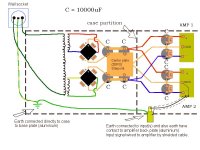
I attach picture about my power supply schematic.
1) Sorry. I don't undestand what you mean 'transformer secondary earth'. I have been connect other rectifier bridge minus(-) and other bridge plus (+) to main capasitors center plate (ZERO).
2) Not directly, but it goes to chassis (case) through input cables shield (RCA). Look my attachment.
3) But where starpoint should be in my amplifier, because I have two big capasitors added close to both amplifier boards, separated from main capasitors.
4) I try that I disconnect AC ground (wall socket ground) but that hum is still hearable.
I noticed that if I disconnect CD-player wire from amplifier input (RCA), hum reduced but still hearable.
Then I tried connect short metal (small chisel) to input (RCA) then hum increases.
If I short circuit input (RCA) to input socket frame (chassis) then hum is like square wave modulated or so. Some high frequencies comes out from my speakers
Attachments
- Status
- Not open for further replies.
- Home
- Amplifiers
- Solid State
- Crescendo protection circuit?