Hello. I am currently working on a crescendo bass clef 8k amp. I have a strange fault that I have not run into yet and can't seem to find the root cause. The output section was blown. I removed all the dead components and check for any signs of life with a low current supply. I had nothing. So I changed the output driver board and the 4x tc4452 drivers and powered the amplifier on and had my low side drive square wave on both banks of mosfets. I went to test it again today to finish the amp and there was no longer any drive waves but when I touch my finger on the lpf or the phase shift knobs, I get a low side square wave with my scope on 8.0ms. If anyone can shed any insight on this it would be greatly appreciated. Thank you
What do you mean by 'low current supply'?
For self-oscillating amps, the circuit may need some sort of signal to start oscillating. Touching something in the circuit may have been enough.
8ms? What frequency?
Were the output FETs in the circuit when testing?
For self-oscillating amps, the circuit may need some sort of signal to start oscillating. Touching something in the circuit may have been enough.
8ms? What frequency?
Were the output FETs in the circuit when testing?
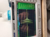
I had the amplifier powered on idling. It was just powered on by a low current supply. No the output mosfets were not in the board. The output only started the square wave when I touched those parts. As soon as I took my finger away, the square wave went away. It was a 75khz square wave and when I keep my finger on one of those 2 adjustment potentiometers it's there. When I take it away it goes away. When I input a signal into the amp it starts to oscillate but as soon as the signal stops it goes away. This is all with the output mosfets out of the board. I have tried it with and without a load attached to speaker terminals as well. Thank you for the reply.
It's odd that you had a 75kHz oscillation with the outputs out of the board. Scopes are notorious for displaying the wrong frequency. Does the 75kHz agree with the display (using the timebase and the divisions on the display to calculate frequency)?
With a 100Hz input signal, what frequency do you see at the gate terminals of the output FETs?
With a 100Hz input signal, what frequency do you see at the gate terminals of the output FETs?
With 40hz, 65hz, and 100hz inputs signals, I get those frequency square waves on the gates of the low side. But as soon as the signal is stopped, the wave goes away. I did try to also install a few of the output mosfets for testing and it's the same thing. The only difference is with them in the board, me touching the adjustment pots didn't produce the wave anymore.
Do you get the drive signal on ALL of the output FET gates (no outputs installed)?
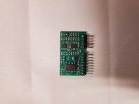
How many header pins does the output driver board have?
How many header pins does the output driver board have?
When you installed the FETs did you have a drive signal (same frequency as input signa) on the high-side FET gates?
What if you set the crossover to the highest frequency, set the gain at the maximum and increase the level of the test signal. does it still do this.
Side note, The same signal would be seen on the high-side source. The high-side gate would have a signal that's about 10v greater on the top of the signal.
Side note, The same signal would be seen on the high-side source. The high-side gate would have a signal that's about 10v greater on the top of the signal.
Yes it still does the same thing with increased signal input and gain set to the max and frequency potentiometers adjusted from lowest to highest.
What is the DC voltage measured across the 4452 ground and VDD when the amp is functioning like it was when the photo was taken?
Last edited:
The DC voltage across the 4452 gnd and vdd when it's like the photo is 12 volts. That is for both the low side 4452's.
Ok so I turned the amp on, it was idling at 10.5v only drawing about 2.5 amps. I had turned the remote off and maybe 30 seconds later turned it back to get the voltages you asked for. When I did that, the amp sat idling at the same voltage but drawing 3.8 amps. The only difference now is that it started oscillating. The voltage you asked for you meant 2nd pin in starting from the left is -12 volts. If you meant 2nd pin in from the right side, it was -10 volts.
When it started oscillating, it had the perfect square wave on the low side and it was perfect on the high side gate as well.
When it started oscillating, it had the perfect square wave on the low side and it was perfect on the high side gate as well.
I am not sure why all of a sudden it would just start working like that. I know when I did turn it back on, the rail voltages were not completely drained to zero.
No it has not but what could have caused something like this? I'd like to see if it can be figured out and repaired so it does not happen again.
You have to find the difference when it works and when it doesn't.
Does it always work normally if it's switched on before the rail voltage drains down?
Does it always work normally if it's switched on before the rail voltage drains down?
Yes, that's the way that it seems. If I turn it on let it build the rails and let the relays click on. Then turn it off for 5 seconds and turn it right back on, it works perfect. I was thinking, could it possibly be on the initial startup, my 10 amp power supply isn't enough for it to fully turn on and that's why it turns on when there is already partial rail voltages?
- Home
- General Interest
- Car Audio
- Crescendo BC8000 output drive