The pairs I was alluding to were Q101-Q102 and Q107-Q108. My thinking is these differential transistors are responsible for input voltage offset errors. Unless I'm missing something, Q103/4 and Q105/10 are relatively benign contributors to offset voltage.
Okay. I found a surface mount resistor that wasn’t soldered to the pad on one end. The right channel is running again. I can conclude changing the well-matched complementary pairs Q101/7 and Q102/6 with random unmatched transistors has not barely changed dc servo output🙂. Dc servo output is around 120mV. I was thinking the servo adjusts the base voltages of Q106 and Q102. Is there a good source on this type of differential input you would recommend?
If I understand the current theory, if Q101-2 and Q106-7 are better matched then the dc servo output should reduce?
Last edited:
That's my thinking with respect to input offset voltage error. Matching of NPN/PNP base currents to achieve near perfect net-0 bias current is a different story.
I'm afraid I have no recommendation of sources to ensure closer base current matching. My suggested addition of bias adjustment resistors in post 35 remains my primary recommendation. Even that is not guaranteed, but my confidence is high.
The suggestion I offered in post 37 is a bit "dodgy"--- it purposely unbalances input voltage offset on the chance that tweaking the emitter resistors might trim base current matching closely enough to satisfy the click/thump problem. Output servo might have to correct a larger offset, but the compromise might suffice. The post 37 idea has implementation simplicity as its sole attraction.
I have an idea for implementing a bias current servo on the PA input, but it's way more complex than the post 35 approach--- it's just more "fun." I'll try to sketch it later, just for grins.
Thanks for your patience and explanation. I think I'm beginning to piece things together. I used to study physics many many years ago. the BS and 1 year of grad school don't matter so much when you don't practice. Anyway, I recall learning some of the basic transistor circuits. I've been trying to relearn and its clear quick learning on google is not working lol. I've started studying from this website http://hyperphysics.phy-astr.gsu.edu/hbase/Solids/trans.html.That's my thinking with respect to input offset voltage error. Matching of NPN/PNP base currents to achieve near perfect net-0 bias current is a different story.
I'm afraid I have no recommendation of sources to ensure closer base current matching. My suggested addition of bias adjustment resistors in post 35 remains my primary recommendation. Even that is not guaranteed, but my confidence is high.
The suggestion I offered in post 37 is a bit "dodgy"--- it purposely unbalances input voltage offset on the chance that tweaking the emitter resistors might trim base current matching closely enough to satisfy the click/thump problem. Output servo might have to correct a larger offset, but the compromise might suffice. The post 37 idea has implementation simplicity as its sole attraction.
I have an idea for implementing a bias current servo on the PA input, but it's way more complex than the post 35 approach--- it's just more "fun." I'll try to sketch it later, just for grins.
1. Matching PNP/NPN base currents is a different story.. What happens when these are poorly matched?
2.Matching same-sex pairs Q101/2 and Q106/7 should reduce the dc servo output voltage thus reducing the voltage spikes (thumping) when the mute relay is turned on/off, correct? For this, I may have found a solution - (https://www.mouser.com/ProductDetail/771-BCM856BSH) with a sot-363 to dip-6 adaptor.
3. I want to hold off on any modification until a fault is found such as poorly matched same-sex pairs.
Last edited:
1. Matching PNP/NPN base currents is a different story.. What happens when these are poorly matched?
2.Matching same-sex pairs Q101/2 and Q106/7 should reduce the dc servo output voltage thus reducing the voltage spikes (thumping) when the mute relay is turned on/off, correct? For this, I may have found a solution - (https://www.mouser.com/ProductDetail/771-BCM856BSH) with a sot-363 to dip-6 adaptor.
3. I want to hold off on any modification until a fault is found such as poorly matched same-sex pairs.
1. It's the mismatch in base currents (e.g. Q101 vs. Q107) that causes the click when the muting is exercised. If base currents were identical, the base current flowing out of Q107 base would flow into Q101 base; there would be 0 current flowing through R101. But in fact with this specific specimen, Q101 base current is about 1% higher and the difference in current comes through R101, producing that -1.2mV drop. Cycling the mute relay shorts the drop, making 1.2mV step changes on each mute/unmute.
2. The matched duals are a good choice, but note that their beta match is spec'd at 90% and voltage match less than 2mV. Your present match is about 99% and the OEM match in the left channel must be even better. The 2mV error will be adjusted out by the output servo. Beta match is key.
3. Actually, I'd argue that the transistors are already pretty well matched. Finding an even better match will be a challenge. Hence, the post 35 suggestion.
Thanks for the explanation. I’ve ordered the dual matched bcm856bs and bcm856bs and SOT-363 to DIP-6 adaptors. The pins will make it easy to measure the beta and Vbe values on my transistor tester. Soldering will be another story, but fun. The datasheet shows minimum beta matching is .9, I’m betting they will be closer to unity based on my earlier beta measurements from the same reels. I’ll attempt to improve matching q101 and q107. Will keep you posted. Thanks again for the help and description of how the input stage works.
When I replaced the original transistors I was focused on matching the complementary pairs q101/7 and q102/6 and did not check if the same-sex pairs q101/2 and q106/7 were well matched. Fingers crossed better matching all pairs will reduce the current and voltage offsets.
🙁
I'm deeply embarrassed that I've been giving you, at best flawed, advice. I've been focused on emphasizing that Q101 and Q107 base currents must be equal to cancel the bias voltage on R101 that makes clicks when shorted by the Mute relay. All true, but the Q101/102 pair is powered by a different constant current than is the Q107/106 pair; a perfectly matched set of four input transistors could still exhibit the bias error if the driving current sources weren't well matched. And an arduous attack on component matching is the hard way to tackle the problem anyway, I believe. 🙁
From the presence of the JP101 connector, I infer there's a connecting cable in the signal path. I suggest simply inserting a good quality film cap in series with this cable, (i.e. between JP101 and the Mute relay) and also shunt the Mute relay with a 1M resistor. In this way, any residual bias on R101 is discharged to ground, so there's no DC present at the relay during Mute cycles. No glitches. (BTW, Bob Cordell's new book discusses output servo techniques nearly identical to you amp. His schematic incorporates a DC block at the amp input.)
Pursuing this vein a bit farther, you mentioned hot switching among various sound sources. To preclude glitches generated when changing program source, make sure there's no residual DC present at the program sources. You can check for any DC presence at output with your DVM; similarly, use a resistance check to confirm presence of a discharge resistance path to ensure any blocking caps are bled to ground to avoid selection glitches. The idea is to ensure that there are no stored biases that have to be absorbed when an input is changed.
No worries! FWIW Q109 and Q111 were replaced recently, as well as all the diodes. Hopefully this round of better matching will fair well. I’ll take a look at the JP101 connections.I have not been able to rule out the dc servo. Regarding post 9, do these values indicate there’s a fault in this particular opamp?🙁
I'm deeply embarrassed that I've been giving you, at best flawed, advice. I've been focused on emphasizing that Q101 and Q107 base currents must be equal to cancel the bias voltage on R101 that makes clicks when shorted by the Mute relay. All true, but the Q101/102 pair is powered by a different constant current than is the Q107/106 pair; a perfectly matched set of four input transistors could still exhibit the bias error if the driving current sources weren't well matched. And an arduous attack on component matching is the hard way to tackle the problem anyway, I believe. 🙁
From the presence of the JP101 connector, I infer there's a connecting cable in the signal path. I suggest simply inserting a good quality film cap in series with this cable, (i.e. between JP101 and the Mute relay) and also shunt the Mute relay with a 1M resistor. In this way, any residual bias on R101 is discharged to ground, so there's no DC present at the relay during Mute cycles. No glitches. (BTW, Bob Cordell's new book discusses output servo techniques nearly identical to you amp. His schematic incorporates a DC block at the amp input.)
Pursuing this vein a bit farther, you mentioned hot switching among various sound sources. To preclude glitches generated when changing program source, make sure there's no residual DC present at the program sources. You can check for any DC presence at output with your DVM; similarly, use a resistance check to confirm presence of a discharge resistance path to ensure any blocking caps are bled to ground to avoid selection glitches. The idea is to ensure that there are no stored biases that have to be absorbed when an input is changed.
Pin 3 is connected ground. Shouldn’t the outputs of U101 and U1 at pin 1 be the same with nearly identical input values at pin 2?
U101:1 = -200mV
U1:1 = -23mV
U101:2 = -0.6mV
U1:2 = -0.5mV
Thanks for the reference to Bob Cordell.
I don't see anything obviously abnormal re voltages in the above post or in post 9. It's reasonable to believe the servos are operating correctly.
A very brief explanation of opamps, at DC frequency: An opamp (OPA) has huge gain, (1E5, often more) and the OPA output voltage is the difference between the + and - pins mumtiplied by this huge gain. Assuming the output isn't forced into a supply rail, the large gain implies the + and - inputs must be essentially equal. So re your data above in which the + pins are grounded, the - pins should also be ~0V--- as you've observed. If you note the voltage at pin 1, you'll find it is the pin 14 voltage X(-1.0)--- i.e. gain of -1.0
A very brief explanation of opamps, at DC frequency: An opamp (OPA) has huge gain, (1E5, often more) and the OPA output voltage is the difference between the + and - pins mumtiplied by this huge gain. Assuming the output isn't forced into a supply rail, the large gain implies the + and - inputs must be essentially equal. So re your data above in which the + pins are grounded, the - pins should also be ~0V--- as you've observed. If you note the voltage at pin 1, you'll find it is the pin 14 voltage X(-1.0)--- i.e. gain of -1.0
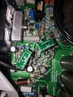
I see, the voltage at pin 14 is another check that the IC is working. Its reassuring that the dc servo no longer a possible cause. Thank you for explaining. I received new reels of bc846bs and bc856bs, as well as the dual matched bcm846S and bcm856bs. And another transistor tester, the same make and model of the one I returned a month ago. Strangely, the bc846b betas are around 400 ( they were 300 a month ago), vs bc856b around 300. When I tested the same batch ( I have new and old Nexperia bc856bs and bc846bs) of bc846s a month ago that tester consistently measured hFE values near 300. The only difference I can think of currently is I installed a fresh 9 volt battery in the tester. Apparently what I thought was a good match is actually a beta ratio of 3/4 and change in Vbe around 30mV(5%). Measurements on bc856bs are consistent over the past month. No radical temperature changes today when I measured bc856b and bc846bs. I went ahead and managed to install the dual transistors. PITA. It’s easier to solder the pcb pads last. I uploaded a photo. The adapter with wires kind of looks like a flower, at least lol. I wasn’t able to measure the duals, also Nexperia. Nothing changes. I think I’m going to pause for a while before any more troubleshooting or repair attempts. The amp sounds great! Just have to remember to turn down the volume before switching inputs and powering on/off. Creek recommends something similar in the manual. Anyway, I really appreciate your help in explaining the details and recommending solutions.I don't see anything obviously abnormal re voltages in the above post or in post 9. It's reasonable to believe the servos are operating correctly.
A very brief explanation of opamps, at DC frequency: An opamp (OPA) has huge gain, (1E5, often more) and the OPA output voltage is the difference between the + and - pins mumtiplied by this huge gain. Assuming the output isn't forced into a supply rail, the large gain implies the + and - inputs must be essentially equal. So re your data above in which the + pins are grounded, the - pins should also be ~0V--- as you've observed. If you note the voltage at pin 1, you'll find it is the pin 14 voltage X(-1.0)--- i.e. gain of -1.0
Attachments
Update, I removed the dual transistor contraption. After another round of matching I managed to significantly reduce the input offsets. The thump in the right channel is at a negligible level, and dc servo output is at 50mV. Cleaning the transistor tester smd pads and adding a little more pressure to each NPN transistor yielded more consistent results. Multiple measurements for precision and accuracy is key. Same-sex pairs matched: hFE1/hFE2 <1%; Vbe1-Vbe2=1mV. Complementary pairs matched: hFE1/hFE2 near 90%; Vbe1-Vbe2 ~5mV. Thank you both for all the help in troubleshooting.
Update: The right channel thumping on changing inputs was remedied when I replaced the internal input wiring with Cat 7 ethernet cable, which has shielded twisted pairs, outer shielding and a drain wire. The right channel thumping was apparently caused by magnetic induction - It didn't help that ribbon cable which powers the speaker relays was routed right next to the right amp in wires.
Correction - it turns out I bypassed the mute relay when I replaced the input wiring - I decided to bypass the preamp-amp switch since it was broken and I never plan to use the separate mode. Anyway, not a good idea because the mute relay essential to the protection circuit. Thumping is back after wiring correctly according to the schematics. It actually happens in both channels, its just louder in the right (since it has a higher bias). The thumping is around 5-10mV at moderate volumes, barely audible. The thumping didn't happen when changing inputs while the mute relay was removed. Is that because the input relays are connected to 100ohm resistors before ground, and the mute relay connects directly to ground?Update: The right channel thumping on changing inputs was remedied when I replaced the internal input wiring with Cat 7 ethernet cable, which has shielded twisted pairs, outer shielding and a drain wire. The right channel thumping was apparently caused by magnetic induction - It didn't help that ribbon cable which powers the speaker relays was routed right next to the right amp in wires.
- Home
- Amplifiers
- Solid State
- Creek Destiny: Right channel thuds on switching inputs and Right channel DC Servo offset increases with volume