Thank you for the information.
Can you check the right channel signal as it enters the balance potentiometer if present check the signal as it enters the treble potentiometer
Can you check the right channel signal as it enters the balance potentiometer if present check the signal as it enters the treble potentiometer
Both left and right channel inputs (Right hand contact facing from the fascia) to the balance and treble pots show a good sine wave. Top of the mylar capacitor c32 leading to c18 shows signal, LH channel C132 does not. What do you suggest, replace C132 and check solder and track to the centre of treble pot? Thanks for your help Audio Service, Al
De-solder on end of C132 where it connects to C18 and see if you have a sine wave on the lifted end of C132.
OK, done. On LH channel 5mv sine wave on C32 where it connects to C18. End of C132 desoldered now at 25mv sine wave, where it was just noise previously.
Thank you for advising, can you re-solder C132 back in circuit and remove Q103 and test it with a multimeter on diode test.
Thanks Audio Service, Q103 performs the diode test fine when desoldered - 600 ohms B to C&E, zero when leads reversed.
Can you check Q103 collector to emitter, if okay check C108 and also the DC voltage levels on the base emitter and collector of Q103 when compared to Q3.
Also check the resistors associated with Q103 if the voltage levels are incorrect.
Also check the resistors associated with Q103 if the voltage levels are incorrect.
Hi Audio Service, its taken a few days to identify all the components correctly and measure voltages. Please see the attached circuit diagram with voltages marked. There is certainly a fault with much higher voltages on the faulty RH channel, although I can't work out the source. Appreciate your advice! Thanks, Al
Attachments
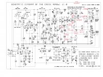
Thank you for the schematic showing the incorrect voltages, at this point I would remove in turn and test out of circuit.
Q103, Q104, Q105.
Q103, Q104, Q105.
Hi Audio service, on checking resistances between components, I had odd readings from R140, supposedly a 2.2k 1/2 watt resistor. There is a 64v drop across it, whereas the equivalent LH channel has 34v drop. The resistance is up at 200k. There is some burning under the PC board, and I'll try changing this first (arrived today) before removing the other transistors for checking. The in-circuit resistances for these seem fine. Cheers, Al
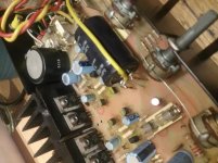
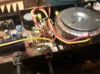
Hi the yellow wire your referring to is connected to the negative terminal of the 4700uF capacitor and then to the ground connection for the speaker terminals.
The wire colour changed depending on the build, I have worked on models where the wire is green, and the speaker ground wire is red.
The wire colour changed depending on the build, I have worked on models where the wire is green, and the speaker ground wire is red.
Hi, all I can help with here is that the negative side of the electrolytic PS smoothing capacitor is the earth return. There are signs of overheating on my PC board where the cap joins, and my earlier version doesn't have the additional wire. This would reduce the current going through the pc board track back to the bridge rectifier. The additional wire is shown on a PC board overlay image I have, I'll post when I've found it. Cheers, Al
Hi Audio Service, it was R140 that was the problem. Out of circuit the 2.2k resistor reads open. I've replaced this and the amplifier is back working again, with the voltage drop of 31v as the LH channel R40. R40/140 and R41/141 are liable to fail in time I think as I've had two fail over the last 35 years. Can't complain though! The running temperature of these is just over 50C with an open case, so even for a 1/2w resistor this is a long term challenge. Good thing is that I have quite a few replacement components now for any further problems.
Thanks for all your help, and all the best for your DiyAudio support! Al
Thanks for all your help, and all the best for your DiyAudio support! Al

- Home
- Amplifiers
- Solid State
- Creek CAS 4040 problems and speaker coupling electrolytic query