Hi Gregory,
in my case i had HUF75639P3 transistors because the original HUF76639P3 transistors were burnt. On HUF75639P3 it was not possible to adjust the voltage on R28 (R128) to 21,5 mV. The amp played like this for about a year. When I changed the transistors, the sound took on a different sound. The bass became strong and tight, the dynamics improved. My Destiny has also revealed more detail in the midrange and has a greater sense of freedom. In my case, the treble also improved, but it could be a bit more. But the sound is still charming. What I noticed is the temperature on the q14 irf9610 (q114) is high, about 50-70 C. Here you need to improve cooling. VR1 is around 15 ohms when idle voltage is at 21.5mV.
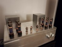
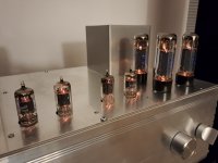
He compares the sound to another of my amplifiers, modeled on the tube amplifier of Mr. Andrea Ciuffoli (photos attached, http://www.audiodesignguide.com/PP2010/PP2010.html). Is very similar now.
Best Regards
Peter
in my case i had HUF75639P3 transistors because the original HUF76639P3 transistors were burnt. On HUF75639P3 it was not possible to adjust the voltage on R28 (R128) to 21,5 mV. The amp played like this for about a year. When I changed the transistors, the sound took on a different sound. The bass became strong and tight, the dynamics improved. My Destiny has also revealed more detail in the midrange and has a greater sense of freedom. In my case, the treble also improved, but it could be a bit more. But the sound is still charming. What I noticed is the temperature on the q14 irf9610 (q114) is high, about 50-70 C. Here you need to improve cooling. VR1 is around 15 ohms when idle voltage is at 21.5mV.
He compares the sound to another of my amplifiers, modeled on the tube amplifier of Mr. Andrea Ciuffoli (photos attached, http://www.audiodesignguide.com/PP2010/PP2010.html). Is very similar now.
Best Regards
Peter
Attachments

Hi Gregory again,
I checked the voltage and temp on R38 (138) i R39 (139). In my amp voltage drops on both channel is about 32V. After a few minutes of starting the temperature is approx 50C. VPWRL/VPWRR is +/-95V so the current is 14,5 mA. Theoretically, the power of the resistor should be enough 0,5W. 1W should be ok. Check voltages on the resistors and supply voltage.
Best Regards
Peter
Hi Peter,
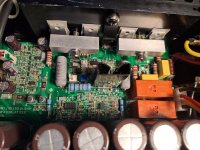
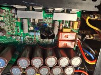
Sorry, I meant the total wattage for those 4 2k2 resistors is around 3 Watts in a small area. On my PCB, After 20 minutes those surface mount resistors got very hot, 80C+, and the heat spread to nearby components. For example, C30 reached 80C. At the time I thought something was wrong with the circuit and/or components. I checked and rechecked all the values, and replaced C30 and C29 to no avail. It turns out, the culprit was the inadequate heat management for those 4 2k2 surface mount resistors. I used an Infrared camera to measure temperatures. After moving the 2k2 resistors, C30 and other nearby component temperatures are 50-60C after warming up.
Regarding Q14, I added a second heatsink which reduced the temperature by 5-10C.
Last edited:
With the low RDS On values I'm thinking there is less heat dissipating from the IRLB4030PBF MOSFETs. Is your lid warm after an hour or so on idle? My heatsinks never get above 45C, except on days when the ambient temperature is above 25C.


I wonder if thermal paste matters here. I use Arctic MX-4 made in Germany (www. arctic.ac). Maybe this will lower the temperature on the power transistors
I used a generic silicone based brand I found at my electronics shop. The thermal camera was borrowed from a tool library. I’m wondering if the lower Rds (On) value for your MOSFETs means less heat. However, It’s only a 1-2C difference for the heatsinks which can be accounted for by error and reading location.
Last edited:
You have a much higher temperature on the power transistors. This may be due to poor heat dissipation from the transistors to the heat sink or a higher value of the Rds(on) resistance. The way is to test the replacement of transistors. 🙁
Is your conclusion based on the photo from the thermal camera? I think you might be mistaking the 2k2 resistors I mounted next to the heatsinks as the power transistors.🙂
Ha now I’m thinking about replacing the thermal paste, it is quite messy lol. Your work is very clean! It’s looks very good!
Nice!
I used silicone thermal insulator pads, I think from mouser.com. I added paste between the transistor and pad and heatsink.
I used silicone thermal insulator pads, I think from mouser.com. I added paste between the transistor and pad and heatsink.
Last edited:
Did you manage to measure the mounting torque of the power transistors against the heatsink? The IRL2910 specs are <1 Nm, I imagine your power transistors are similar. I ended up just adding a small amount of pressure past snug.
Last edited:
- Home
- Amplifiers
- Solid State
- Creek Audio Destiny: Help with adjusting VR2