Looking at the TIP35 (etc) data sheet, a single pair of TIP35(ABC) is good for about +/-25V for 8 Ohms and about +/-15V for 4 Ohms. The history of "solid state" amplifiers is full with SOA failures because designers were over optimistic or simply failed to understand secondary breakdown. At ~+/-40VDC, TIP35 is good for about 1.5A, and it needs to be about 5A. So you can parallel 3 or 4 pairs (with separate Re), or pick a newer transistor.
I wish I could see the schematic because it sounds like there may be more to the failure.
Good luck.
I wish I could see the schematic because it sounds like there may be more to the failure.
Good luck.
Scematic
Hi joaobernarda.
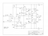
I attach the schematics sent to me by Creek. They refer to the latest production model (revision 6). If you have an earlier version the component numbers may be wrong but you can usually manage to work out which is which. I had the mark 1 version. The numbering on this starts from the opposite end for the power amplifier, so tr17 was tr1 in mine, tr18 was tr2, tr15 was tr3, tr16 was tr5, tr10 was tr4, tr13 was tr6 and tr14 was tr7.
I would recommend that if you have a blown amp you change all of these. Gain match tr15 and tr16 using the transistor section of a multimeter. You really should gain match tr17 with tr18 but this must be matched for current gain and that is incredibly difficult to do.
It is a good idea to also check tr 9 (tr8 in my early version. If this is fine don't replace it. Modern versions of this transistor run really hot.
Hi joaobernarda.
I attach the schematics sent to me by Creek. They refer to the latest production model (revision 6). If you have an earlier version the component numbers may be wrong but you can usually manage to work out which is which. I had the mark 1 version. The numbering on this starts from the opposite end for the power amplifier, so tr17 was tr1 in mine, tr18 was tr2, tr15 was tr3, tr16 was tr5, tr10 was tr4, tr13 was tr6 and tr14 was tr7.
I would recommend that if you have a blown amp you change all of these. Gain match tr15 and tr16 using the transistor section of a multimeter. You really should gain match tr17 with tr18 but this must be matched for current gain and that is incredibly difficult to do.
It is a good idea to also check tr 9 (tr8 in my early version. If this is fine don't replace it. Modern versions of this transistor run really hot.
Attachments

I would cross-couple the TIP35 and TIP36, and if it dies again, find newer better SOA transistors, something like 2SC5200/2SA1943. And the drivers need to be something like MJE340/350, ie ~10 Watt transistors c/w heat sink.
Last edited:
I've just re-read my replies here and realise that I still don't know why both channels failed. If the output stage of one channel went short that would lower the supply voltages wouldn't it? It is many years since I retired as an AV technician but I remember we never had amps with both channels blown. Both supply lines are 42.5 volts as the circuit suggests. (This gives 85 volts across the power amp stage - 80volt TIP35B transistors is disappointing here). Thanks for your help but I might give up on this one! Mooly I've just re-read your first response - ignore my answer about the lamp.
There was a case of breakdown of the diode bridge, after which the output voltage doubled ...
You may have had a mains power surge. When I was doing hardware QA, we required products to handle a 20% voltage surge. An extra 20% would be 102VDC, which would kill your TIP35/36.
TIP36C
My version 1 had TIP35B transistors. It is perhaps surprising that it worked as long as it did. Since fitting TIP35C it has been fine. It is my view that the relatively high supply voltage was unnecessary. Most semiconductors before the output pair run hot. They seem to have updated the cheaper 4040 by increasing the supply voltage and using TIP35/36 instead of TIP3055. I have changed the first stage amp transistor for a ZTX type and matched the constant current supply transistor with the complementary ZTX. Runs cooler and sounds better.
I have an Exposure power amp that has a similar circuit but all components run cool and it sounds better too. The supply voltage in that is just a bit lower.
Try this attachment
R82 in the power amp input section is intriguing - it seems to increase output offset for no obvious reason? Compensation perhaps?
Yes Mark, it seems to have no obvious purpose. It would seem to me to interfere slightly with the negative feedback as well as your observation. I have never seen this 'feedforward' before. I have tried removing it and the effect on the sound was very tiny. No voltages changed. My mark 1 version had this but not the r81 (22k ) making it all the more intriguing.
In my amp tr9 was a bc560. This had blown and the replacement got hot in use.. Replaced with the bc640 from Creek's circuit spoiled the sound a bit and it got equally hot. I have replaced it with a ZTX753 as used by Naim et al. It still gets hot but the amp sounds a bit better. Tr12 had to be replaced on one channel. The replacement runs hot but the original Philips doesn't. I tried various makes of transistor for this. The original Philips stays cold in either the left or the right circuit but modern replacement gets hot. I replaced that with a ZTX653. Still hot but sounds better.
I have serviced many amps and not found one where the predriver stages get this hot (too hot to touch). It seems a hastily produced circuit.
- Home
- Amplifiers
- Solid State
- Creek 5050 schematic