Hi there,
since I made already good progress in my modular Arduino based passive pre-Amp project (nearly all stages are in prototyping mode), it is time for me to go to the volume stage.
I want to go with the MUSES72323.
I know that there are already several threats about it, but I did not find one that was really what I am looking for, so I started to dig in by myself.
Goals:
Order a MUSES from Mouser, solder it to a PCB I'll design, control it via Arduino.
Following my idea, I do not want to have anything within my signal way besides the MUSES itself.
I know that the datasheet suggests coupling caps on both sides and output buffers on the output.
But I know that several successful projects (mostly for the MUSES72320) did it without.
But please give me some input!
I know that coupling capacitors are needed to block DC in the signal.
Normally, I expect nearly all source devices to have output coupling capacitors (at least I know that my DIY XONO have some, both of my DAC have it, my old AVR have them (I did not open the new one yet).
So why should I place one in addition here?
Same for the output capacitors.
Most power amps I had on my bench had input coupling capacitors.
And even not, where do we expect the DC to come from?
Or is it known that the MUSES itself tends to create DC?
I simply would prefer to not go, again, into the coupling capacitor rabbit hole + I simply don’t want the pre-amp to change the signal in any way besides the volume.
Also for the buffer, if I want the MUSES to be just a "Volume Pot" I do not see a need.
Specially, when it in fact should just replace a volume pot in an existing chain.
Can you give me some ideas about this?
Regarding the schematics, I went through several other projects and build up this schematic:

Did I miss anything there or do you think it is good to go?
Do I get it right that GND from the Arduino and GND for the Signal / 15V PSU would be completely separated here?
(I managed so far in the pre-amp that Signal and Digital is completely separated (even there will be one jumper point in case there are issues with the separated GNDs).)
I'm happy for your feedback!
And yes, in case that this works we can talk about sending PCBs to others.
Regards,
Felix
since I made already good progress in my modular Arduino based passive pre-Amp project (nearly all stages are in prototyping mode), it is time for me to go to the volume stage.
I want to go with the MUSES72323.
I know that there are already several threats about it, but I did not find one that was really what I am looking for, so I started to dig in by myself.
Goals:
Order a MUSES from Mouser, solder it to a PCB I'll design, control it via Arduino.
Following my idea, I do not want to have anything within my signal way besides the MUSES itself.
I know that the datasheet suggests coupling caps on both sides and output buffers on the output.
But I know that several successful projects (mostly for the MUSES72320) did it without.
But please give me some input!
I know that coupling capacitors are needed to block DC in the signal.
Normally, I expect nearly all source devices to have output coupling capacitors (at least I know that my DIY XONO have some, both of my DAC have it, my old AVR have them (I did not open the new one yet).
So why should I place one in addition here?
Same for the output capacitors.
Most power amps I had on my bench had input coupling capacitors.
And even not, where do we expect the DC to come from?
Or is it known that the MUSES itself tends to create DC?
I simply would prefer to not go, again, into the coupling capacitor rabbit hole + I simply don’t want the pre-amp to change the signal in any way besides the volume.
Also for the buffer, if I want the MUSES to be just a "Volume Pot" I do not see a need.
Specially, when it in fact should just replace a volume pot in an existing chain.
Can you give me some ideas about this?
Regarding the schematics, I went through several other projects and build up this schematic:
Did I miss anything there or do you think it is good to go?
Do I get it right that GND from the Arduino and GND for the Signal / 15V PSU would be completely separated here?
(I managed so far in the pre-amp that Signal and Digital is completely separated (even there will be one jumper point in case there are issues with the separated GNDs).)
I'm happy for your feedback!
And yes, in case that this works we can talk about sending PCBs to others.
Regards,
Felix
Hi Felix,
I've compared your schematic with the data sheet and my versions of the Putzeys preamp/Muses 72323 volume controller. As far as I can see you've got it right.
When you lay out your board, I suggest
All the best,
Geoff
I've compared your schematic with the data sheet and my versions of the Putzeys preamp/Muses 72323 volume controller. As far as I can see you've got it right.
When you lay out your board, I suggest
- include provision for input coupling capacitors (22uf 25V bipolar suggested). This gives you the option to fit bypass links in place of the electrolytics then, if you find there's a problem caused by direct connection of the inputs, you still have the ability to fit the coupling capacitors.
- locate the electrolytics to provide reasonable access to the MUSES pins so as to enable easier rework of its device pin solder joints
All the best,
Geoff
Last edited:
Hi Geoff,
yeah that might be a good option.
I think I'll place a Elko place together with a foil shunt place and a solder point in parallel.
Makes it more flexible for others.
But do you have an idea about the output caps and the buffer?
Regards,
Felix
yeah that might be a good option.
I think I'll place a Elko place together with a foil shunt place and a solder point in parallel.
Makes it more flexible for others.
But do you have an idea about the output caps and the buffer?
Regards,
Felix
Do these help?Hi Geoff,
yeah that might be a good option.
I think I'll place a Elko place together with a foil shunt place and a solder point in parallel.
Makes it more flexible for others.
But do you have an idea about the output caps and the buffer?
Regards,
Felix
Geoff
Attachments
Definitely good input😁
Reminds me that I forgot some fouls in the power supply.
I think I'll make the Muses bottom mounted while all other components will be top mounted (I think I'll go with through hole only for everything else to improve the DIY options). That should help in case some work on the pins is needed.
I was mainly interested if you could explain the output cap and buffer thing😅
Regards,
Felix
If you use an FET op-amp for an output buffer, you don't need a capacitor between the Muses 72323 output (see the data sheet example and my schematic). Given the use of a decent op-amp buffer, its output dc offset will be very low and the output from the buffer will be on or very close to 0V. IF your power amp has an input coupling capacitor, you don't need an output cap.I was mainly interested if you could explain the output cap and buffer thing😅
Mounting the Muses chip on the reverse side to the other components will ease construction. The downside is it can make fault-finding and rework that bit more difficult.
I'm a fan of SMD. I'm at the tail-end of my 75th year and having taken the time to learn and practice, I'm far more comfortable building with it. I do wish my contemporaries would get on board with it. If they stick to through hole components, they will have problems for the future as more and more components become only available as SMD.
Last edited:
If you want a buffer (whether input or output), I suggest using a unity gain stable FET op-amp as a non-inverting amplifier. An OPA1642 would be a suitable very low noise candidate.
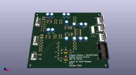
Hey there, I finally managed to create a PCB, based on the schematics.
What do you think?
Schematics:

Boardplan:
.png")
Render:
.png")
.png")
The parts hab been also already arrived😅
Felix
What do you think?
Schematics:
Boardplan:
Render:
The parts hab been also already arrived😅
Felix
Yes.Or is it known that the MUSES itself tends to create DC?
It is also best buffered, please see the datasheet. Local voltage regulators close to the IC would not hurt.

Jean-Paul's response is spot on regarding buffering and local regulation. Getting the decoupling as close as possible to the device pins would help too.
On a simplistic point, how will you mount this(e.g. M3 mounting hole on all corners)?
On a simplistic point, how will you mount this(e.g. M3 mounting hole on all corners)?
Last edited:
It will be seated with the pins on the preamp board directly.
Regarding the buffers, I already tested a Muses Module from the German Analog Forum without buffers and cabs, and it worked fine in my chain.
I just want to have all the control functions on my own, so I don't use it.
Regards,
Felix
Regarding the buffers, I already tested a Muses Module from the German Analog Forum without buffers and cabs, and it worked fine in my chain.
I just want to have all the control functions on my own, so I don't use it.
Regards,
Felix
Don't you know Arduiono?^^
For me it is an important point that I do not want to go through the capacitor and IC rabit-hole.
For example, my Power-Amp has already an input cap stage, same as most of my devices has them on their outputs.
As I normaly go with Janzen Superior, I would have then two choices:
Place huge and expensive Jantzen caps on the board
Blow the whole point about avoiding polarized caps in my chain
Same for the buffer...I tried within the last years the most to get rid of ICs...
Regards,
Felix
You have to take into account that either you yourself (by mistake) or someone else will connect the device to a random other device. Then DC is very unwanted. Devices should never be have considerable input and/or output DC offset. This really should be a design criterium.
There is no cap/IC rabbit hole. There are defects caused by DC carrying devices and impedances to care about hence the buffering. Also think of feedback of DC from the load that has DC offset back to the MUSES72323 without caps!
No one forces you to use expensive Chinese caps, you can use EU made film capacitors that are both cheap, very good and small in 5 mm pitch. Anything better than a burnt woofer. Most modern sources have DC coupled outputs but power amplifiers have the input caps as last line of defense against sudden failure because of DC.
BTW the MUSES72323 IS an IC.
Last edited:
For sure the Muses is an IC.
To use my wording more precise, I meant OP-Amp.
The Muses itself handles the audio signal completely passive, since it acts just as an resistor array.
With the buffers, we would get active components in the signal chain.
Thos is what I would like to avoide.
Also this is the point about the caps.
I get why we might need it, if we have the buffers in place, but not where the Muses can produce DC in "passive mode".
It is more or less in that way just a poti.
And we would not place caps before and behind a poti.
The only reason for an output cap in that mode is that rhe shifting of the resistance gives a short and low DC impulse.
You can hear it as a slight electric crack sound.
Very similar to the Cambrige Azure AVRs.
On that point, it is a question of taste.
I prefer to have them, but no extra cap.
Also I measured the (buffer and cap free) muses I had here for testing and did not see any permanent DC.
Since this board I create will just be a poti as one part, I want to keep it as low as possible.
For my project, it will sit on another board (that has to be created).
So I will continue with the small board and measure the DC again.
If I see DC, I can plan caps on the I/O board, or places as option, for other projects.
Since the idea of the board ist to use it in DIY projects as a part, I see the responsiblety to check if stages need to be de-coupled.
For example if someone places it between the pre-amp and power-amp stage, there should be thoughts about this already existing in the amp schematics itself.
Regards,
Felix
Thanks,
My Russian is not the best (or lets say I know about 3 words😁, but auto-translate and one of my students (she is also from Ukraine) helped😂.
Yeah, that comes pretty close to what I am doing.
I plan a little bit more and complicated stuff like rule-based input routing, serial based connection to my Denon AVR, DAC controlling, etc. and ended up with a nice little (ok, I'm about 1,5k lines) modular based software for my Arduino (I go with the mega pro).
Just the Denon thing and the Muses is not integrated yet.
And a friend asked me if we could integrate a impedance and resistor controlmodule for his Xono.
For the Muses I intend to stick close to the stuff from geoffw1 here in the Forum.
The only thing I dropped in general is the idea to make the whole thing configurable by display.
It will be IDE only (as far as I go).
But my plan is to drop all the code open in the end here and in the Analog-Forum (my home forum).
Regards,
Felix
No. It certainly is not just a potentiometer as it works differently. Don't believe me, believe the datasheet.I get why we might need it, if we have the buffers in place, but not where the Muses can produce DC in "passive mode".
It is more or less in that way just a poti.
Some ICs have DC offset and some ICs react to DC offset from what is connected to them.
Last edited:
Then replace Arduino to ESP32, like meI plan a little bit more and complicated stuff
From what I read from the datasheets and the presentation video of Nisshinbo, the Muses greates a resistance between in and out, not amplifies the signal in an active way.
Nisshinbo explicitly advatises the benefit of having all active signal handling parts outside the Muses chip.
I do not see that the the Muses performs an active conversion of the signal.
About the ESP32: I had it on the list, but I need a little more pins😅
Also I don't need Wifi or BT.
Regards,
Felix
- Home
- Source & Line
- Analog Line Level
- Creation of a MUSES72323 Volume Board for Arduino