No schematic, but a peek at the type of components suggests a circuit similar to the one at post #12.
Apparently, it is that circuit with the addition of load stabilizing caps, at least. I posted for someone who does not want to point to point a perfboard. It's cheap and ships ePacket--~2 weeks.
In my case, the circuit snippet I posted is part of a bigger picture, and sits within a custom PCB together with other components.
I never used a virtual ground for lower noise circuits aiming also at high slew rate so i thought to ask something that i don't fully understand:
Using a very high precision op amp like LT1013 with very low slew rate(0.2v/us) and a diamond buffer in its feedback loop than paralleling with big value capacitors on the output is nuling the op-amp bandwidth as this article say at the end:
file:///C:/Users/neanderthal/Downloads/Virtual%20Ground%20Circuits.htm
But i think that I need some higher speed for the ground regulator while the high precision dc circuit is going to provide a high precision for biasing the circuit so i don't know if i should really care about the op-amps bandwidth reduction which is already very low. Should i rather wory for the op-amp's stability or how would i need to think about it? Will the LT1013 slew rate and badwidth count?
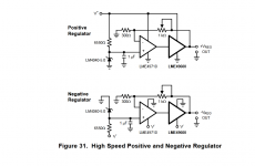
If i go the LME49600 app way with a higher slew rate yet lower offset op-amp i lose the ground DC level precision that LT1013 offers me.
Will some high value capacitors placed at the output compromise the LT1013 performance by reducing its bandwith even more and finally compromising the buffer? if i use lme49600 in the LT1013 feedback loop i do understand that the op-amp will not act on the buffer output impedance anymore but the capacitors at the output will take care about that while the buffer is going to provide a somehow lower output DC resistance than just some resistors while a simple buffer paralleled with the putput capacitors won't have the dc precision without the op-amp .
I still lean to a simple divider with 1kuf capacitors paralleled with 4k7 resistors, but the load is 80k paralleled with the positive rail resistor while the op-amp's inputs of the circuit that i need to ground are somehow sensitive to bias offset..
Using a very high precision op amp like LT1013 with very low slew rate(0.2v/us) and a diamond buffer in its feedback loop than paralleling with big value capacitors on the output is nuling the op-amp bandwidth as this article say at the end:
file:///C:/Users/neanderthal/Downloads/Virtual%20Ground%20Circuits.htm
But i think that I need some higher speed for the ground regulator while the high precision dc circuit is going to provide a high precision for biasing the circuit so i don't know if i should really care about the op-amps bandwidth reduction which is already very low. Should i rather wory for the op-amp's stability or how would i need to think about it? Will the LT1013 slew rate and badwidth count?
If i go the LME49600 app way with a higher slew rate yet lower offset op-amp i lose the ground DC level precision that LT1013 offers me.
Will some high value capacitors placed at the output compromise the LT1013 performance by reducing its bandwith even more and finally compromising the buffer? if i use lme49600 in the LT1013 feedback loop i do understand that the op-amp will not act on the buffer output impedance anymore but the capacitors at the output will take care about that while the buffer is going to provide a somehow lower output DC resistance than just some resistors while a simple buffer paralleled with the putput capacitors won't have the dc precision without the op-amp .
I still lean to a simple divider with 1kuf capacitors paralleled with 4k7 resistors, but the load is 80k paralleled with the positive rail resistor while the op-amp's inputs of the circuit that i need to ground are somehow sensitive to bias offset..
Attachments
Last edited:
I know their circuit...i already read abou 10 pages on this subject ..still don't really understand this subject in depth.My basic question is about the use of high value output capacitors along with op-amp closed loop.
Maybe just getting the buffer out of the feedback loop and still using high value output capacitors would solve the problem retaining some of the precision of the op-amp although the buffer itself might add some offset, but i think that the op-amp output low impedance will make the buffer output impedance go a bit lower too and also its noise , compared with just some higher value (22kohm) resistors biasing the buffer.Then for the high frequency output impedance the outpout capacitors will be good enough.
- Home
- Amplifiers
- Solid State
- Creating the 'virtual ground' in a single supply preamp/amp circuit???