Hi,
This question is the other way around. I have a +16-0- -16 power supply. In this lunchbox 0 is connected to ground. I want to make a discrete board with a 0v connected to ground and a positive rail of 30V.
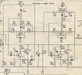
Is there and easy way to do that? The goal is to create this eq board. A copy of a 1970 eq design.
Or can i feed this circuit without connecting the audio ground to zero?
Excuse my beginner level i display here..
This question is the other way around. I have a +16-0- -16 power supply. In this lunchbox 0 is connected to ground. I want to make a discrete board with a 0v connected to ground and a positive rail of 30V.
Is there and easy way to do that? The goal is to create this eq board. A copy of a 1970 eq design.
Or can i feed this circuit without connecting the audio ground to zero?
Excuse my beginner level i display here..
Attachments
Last edited:
Simple answer is that it would help to see the PSU circuit details.
Can a -/+16v supply provide a single 30 or 32v rail... simple answer yes, more complex answer... it depends what else you connect to it.
Can a -/+16v supply provide a single 30 or 32v rail... simple answer yes, more complex answer... it depends what else you connect to it.
Thanks for your reply
The + and - 16 bipolar comes from a Midas L6 500 series lunchbox. It is a switch mode power supply. I have no diagram.
The board i make should work in all other lunchboxes too.
Does this help?
The + and - 16 bipolar comes from a Midas L6 500 series lunchbox. It is a switch mode power supply. I have no diagram.
The board i make should work in all other lunchboxes too.
Does this help?
Last edited:
OK, I think I understand now what you are trying to do...
You can construct the discrete tone control as shown and connect +V to the +16 volt line and you connect 0V to the -16 volt line.
The input, interstage and output coupling caps (the electrolytic ones) will need their polarity checking and altering to suit the operating conditions of the circuit.
For example the voltages on TR4 and TR6 emitters may be at a positive or negative voltage... we don't know what... although they should be close to zero volts. So you have to check and fit the caps accordingly. The output should be connected with a 100k resistor to the 0V line of the new supply so as to provide a ground reference for the output coupling cap.
The audio input and output now all reference to 0v on the -/+16 volts supply, not the old 0V which is now at -16 volts.
As long as the rails are clean it should work OK. If the rails are noisy then the -16 volt rail may couple some of that noise into the audio chain... you will only know by trying it.
Thanks for your reply!
The PS is a 500 series Midas L6 lunchbox. It is a switch mode PS but i have no schematics. It would have to work on any other 500 series supply.
This would be connected unbalanced:
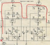
+ line level before C6 or after and junction R11/R14
Ground to 0V/Ground, other end of R11.
Output after R31 with a 47K resistor to ground/0V
It would also be awesome if i can make this schematic work with a dual supply too.
The PS is a 500 series Midas L6 lunchbox. It is a switch mode PS but i have no schematics. It would have to work on any other 500 series supply.
This would be connected unbalanced:
+ line level before C6 or after and junction R11/R14
Ground to 0V/Ground, other end of R11.
Output after R31 with a 47K resistor to ground/0V
It would also be awesome if i can make this schematic work with a dual supply too.
Yes its unbalanced.
What I describe is making it work on the dual supply. The circuit runs across the -/+16 volt rails and the electrolytic coupling caps are fitted to suit what happens.
Looking closer and R11 might be better now tied to the new 0V line (ground) so as to avoid any DC current flowing in the pots. That would also technically provide the wanted DC reference tying the output coupling cap to ground.
The input must retain AC coupling which I think is off the page on your diagram.
OK, I think I understand now what you are trying to do...
You can construct the discrete tone control as shown and connect +V to the +16 volt line and you connect 0V to the -16 volt line.
The input, interstage and output coupling caps (the electrolytic ones) will need their polarity checking and altering to suit the operating conditions of the circuit.
For example the voltages on TR4 and TR6 emitters may be at a positive or negative voltage... we don't know what... although they should be close to zero volts. So you have to check and fit the caps accordingly. The output should be connected with a 100k resistor to the 0V line of the new supply so as to provide a ground reference for the output coupling cap.
The audio input and output now all reference to 0v on the -/+16 volts supply, not the old 0V which is now at -16 volts.
As long as the rails are clean it should work OK. If the rails are noisy then the -16 volt rail may couple some of that noise into the audio chain... you will only know by trying it.
Ok, this is what i hoped for!
I posted in the meantime. I understand well: Audio input before C6, R11to the new 0V, not the old which will be now -16. Measure polarity of the three coupling caps, after R31 a 100K to the new 0V.
Is it good idea to increase R11 to 100K as well?
Maybe i put some elco's and mica between -16 and +16 to clean the rails a little?
R11 is part of the network the pots connect to and so should remain at 22k. Changing it will alter the behaviour of the controls.
If you look at the circuit you can see there is a resistive path from C19/R31 through all the pots and R11 to ground and so we shouldn't really need another resistor to the new 0V. It is only to stop the output of the cap 'floating' and that is taken care of by the resistive path that already exists.
The best way to clean the rails would be to add a 100 ohm (like R20) into the negative feed and add a small 0.1uF film cap across C13.
I'll look in later...
Good luck 🙂
Hi again,
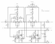
I made a first draw. I connected R1 to 0V and added an 100K to the output. Do i need an extra cap there? R23 was already in the original schematic.
So could this be right?
Thanks
I made a first draw. I connected R1 to 0V and added an 100K to the output. Do i need an extra cap there? R23 was already in the original schematic.
So could this be right?
Thanks
Oh i see, my draft is was attached. So R22 in this one can go you mean?
Attachments
Last edited:
Yes, that's the sort of thing.
Just watch the values... C14 is 100nF which is 0.1uF, not 1uF Same for C7. Check them all carefully.
C11 on your diagram is reversed.
Depending on what the final voltages are your 47uF may need to be fitted the other way around. We don't know at this point.
The emitter volts could be +1 or +3 or -2 or -4 volts and that determines which way around the caps go.
When it is built and working measure the voltage across each electrolytic and fit it according to the measured polarity.
Only typo's I know 🙂
Yes! Thanks again.
I see c11 is reversed and i will measure C4 C10.
Does R22 harm?
I increased C2 and C".." to extend low end. Also C4 and C10.
Or do you think this is not a good idea?
Another question, what route would you advice if i want to turn this into a real pcb?
I see c11 is reversed and i will measure C4 C10.
Does R22 harm?
I increased C2 and C".." to extend low end. Also C4 and C10.
Or do you think this is not a good idea?
Another question, what route would you advice if i want to turn this into a real pcb?
R22 does no harm but it is seen as a load resistor so don't go to low with it.
If you increase the caps then you move away from the original circuit you liked so much 🙂 and that may or may not improve things.
The PCB is something you will have to play around with to get a suitable layout. It's time consuming. I used to use paper and pencil but now would lay it out 'freehand' using a something like 'Diptrace' which is free to download. Its a learning curve though, not a quick job.
Place the pots on the board first so they are where you want them and then work around with parts. Its a simple circuit and there won't be any stability or weird layout issues.
- Home
- Amplifiers
- Power Supplies
- Create single power supply from a supply