Hello,
The resistor will give you a 6 DB filter and the choke will give you a 12 DB filter.
Carefully read the post #11
A better quality choke will give a better sound.
IF you still have to buy your power transformer it is a VERY GOOD idea to go for a choke input.
You mention a choke 20 Henry 120 ohm. Even for a mono amp with two Kt88 there will be a lot of current running so the choke will be big.
There are a few Lundahl LL1638 available here on swap meet rated for 400 mA.
Like you can read in #11 a choke input with the RIGHT bleeder resistor will be even better. Much better. With choke input the transformer needs a much higher AC output but the current rating can be much lower because the choke input will keep the current at the same level all the time as you see and possibly read in the attachment.
Greetings, Eduard
.png")
The resistor will give you a 6 DB filter and the choke will give you a 12 DB filter.
Carefully read the post #11
A better quality choke will give a better sound.
IF you still have to buy your power transformer it is a VERY GOOD idea to go for a choke input.
You mention a choke 20 Henry 120 ohm. Even for a mono amp with two Kt88 there will be a lot of current running so the choke will be big.
There are a few Lundahl LL1638 available here on swap meet rated for 400 mA.
Like you can read in #11 a choke input with the RIGHT bleeder resistor will be even better. Much better. With choke input the transformer needs a much higher AC output but the current rating can be much lower because the choke input will keep the current at the same level all the time as you see and possibly read in the attachment.
Greetings, Eduard

Hello,
Small '' translation ''
Measurements taken at point B in the top drawing.
Left screen top ripple, nice shape , 0,6 volts with 180 mA load current choke input 2 Henry first cap 100 microfarad .
Left screen bottom ripple, saw tooth shape 5 volts without the choke
Right screen top current stays close to 180 mA ALL the time with choke input.
Right screen bottom no input choke current 180 mA but peaks up to 425 mA present in transformer, diodes. Of course also present in the wires connecting all these parts and in the first cap which will have to work much harder.
After point B you could put a choke if you are not using an input choke but the result will NEVER be the same. With the choke input, with sufficient Henry plus a bleeder it will be a good idea to add just one RC filter.
From what i tried in the past the best result can be had by investing in a nice input choke like the LL1638 of course you will have to know the current being drawn by the circuit and then you have to calculate the bleeder resistor.
Greetings, eduard
A few calculations, and an example of the results.
You only need to tailor the selection of choke Henry, DCR, and current ratings, and re-do the calculations to find the results for your B+ supply.
A Hammond 193H, 5 Henry 200mA choke has 65 Ohms DCR.
At 100 Hz full wave rectification (50 Hz power mains), the choke has . . .
3140 Ohms of inductive reactance, plus 65 Ohm of DCR.
For approximation, lets say the total choke impedance is 3200 Ohms.
A 47uF capacitor After the choke, at 100 Hz full wave rectification has 53 Ohms of capacitive reactance.
No matter what the ripple voltage of the capacitor is Before the Choke is . . .
We have a Ripple Voltage Divider of: 53/(3200 + 53) = 0.0163
If the first capacitor's ripple voltage is 300mV, then, after the choke that is followed by a 47uF capacitor, we have 0.300V (0.0163) = 0.0049V (4.9mV ripple).
The only way to get a CRC with the same ripple voltage, that uses the same input and output capacitors, is to use a 3253 Ohm resistor!
But the voltage drop in the 3253 Ohm resistor is Extremely Large.
The low B+ voltage can run a low voltage capable output tube Plate.
Take your pick of DC Voltage drop, versus ripple voltage.
Choke?
Resistor?
And, which part runs cooler, the choke, or the 3253 Ohm resistor?
The voltage drop in the resistor, will require a higher secondary voltage from the power transformer to get the same B+.
$pend the money, Find the $pace, live with the weight, live with the magnetic field $pray, and u$e a choke.
If you are a de$igner trying to compete with the re$t of the manufacturer$ out there, and $till make a profit, you might $elect a Re$iStor in$tead of a choke, and u$e much much more capacitance for each filter cap, to get the ripple voltage that you want.
The choice is yours.
Just saying
Last edited:
Hello,
This is lcrc supply going into a low voltage shunt supply.
Ripple is around 3 milivolts and if you remove the input choke it will go up to around 145 mv .
Allen Wright used to call chokes electronic flywheels. They will kind of store energy and keeps " things at a steady level "
A choke will work forever another big advantage.
All the Lundahl chokes i used so far also work perfect for choke input supplies.They don't disturb things in their surroundings because of the way they are constructed. They are even better than the Tango chokes designed to be used as choke input.
Greetings,Eduard
P.s As you can see better have a choke that is bigger than the transformer. Of course this is a 10 volt 600mA transformer so probably a high voltage transformer with some heater windings too will be bigger.
@Frederico-Acardi: PSUD is your friend. The simulation waveforms are pretty well bang on the money. Highly recommended.
https://www.duncanamps.com/psud2/
https://www.duncanamps.com/psud2/

The Hammond numbers are rules of thumb dating to at least the 1970s, which assume ordinary diodes (what if you use Schottkys?) along with average values of transformer series resistance and choke resistance if needed, useful when putting together a circuit when simulation meant building a Spice netlist on punchcards and booking mainframe time. There's no more need for guessing with free simulators (did I mention free?) a mouse click away.
By the way, ici une réponse au livre de Céline: https://www.newyorker.com/culture/cultural-comment/a-newly-discovered-celine-novel-creates-a-stir
By the way, ici une réponse au livre de Céline: https://www.newyorker.com/culture/cultural-comment/a-newly-discovered-celine-novel-creates-a-stir
Hello,
The link to Hammond site was just a way to show how much difference there is between a supply with capacitor input and one with choke input.
Clearly showing that choke input will give all other parts a much easier life.
Lundahl is one of the few companies that will mention on their transformer data files that current rating is close to 65% with cap input and something like 95 % with choke input. The current rating being given for transformers has to be diminished considerably for the way most people are using it here..
Nice link!!
Greetings,Eduard
DSP_Geek,
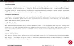
Take a 350V-0-350V power transformer secondary, wire it for full wave rectification, and use a cap input filter (CRC or CLC).
Use old diodes that have perhaps a 1.0 volt drop. You get almost 494VDC out at the first capacitor.
Instead, use Schottky diodes that have perhaps a 0.3V drop. You get almost 494.7VDC out at the first capacitor.
What is the difference?
About 1 layer of the onion, on a large onion with 1000 layers.
I admit, for a given power transformer, if schottky diodes are used for a 5VDC power supply, the voltage would be too low if you use the old technology diodes.
Do not pooh-pooh old numbers.
Pi is still Pi, and there are many other things do not change.
Yes, Quality is dead, and nobody noticed, there has been no memorial service, and the burial is not scheduled yet.
eduard,
You missed a very important point of the Hammond schematics.
Look very carefully, it does show how much DC Amps you get to safely use, versus the AC Amp rating of the transformer secondary.
In conclusion, Lundahl is not the only one, Hammond does it too.
Just my interpretation of the Hammond numbers (even if it is more obscure, or hard to understand.
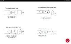
And there are lots more schematics on the Hammond site, for even more circuit configurations.
You missed a very important point of the Hammond schematics.
Look very carefully, it does show how much DC Amps you get to safely use, versus the AC Amp rating of the transformer secondary.
In conclusion, Lundahl is not the only one, Hammond does it too.
Just my interpretation of the Hammond numbers (even if it is more obscure, or hard to understand.
And there are lots more schematics on the Hammond site, for even more circuit configurations.
Hello,
Dont worry i saw it clearly they put a clear relationship between AC current rating and available DC after adding the rectifier/ caps/choke.
I remember buying old English HT transformers with current rating specified when used with choke input.
Greetings, Eduard
Dont worry i saw it clearly they put a clear relationship between AC current rating and available DC after adding the rectifier/ caps/choke.
I remember buying old English HT transformers with current rating specified when used with choke input.
Greetings, Eduard
DSP_Geek,
Do not pooh-pooh old numbers.
Pi is still Pi, and there are many other things do not change.
Yes, Quality is dead, and nobody noticed, there has been no memorial service, and the burial is not scheduled yet.
Wellllllp, that shore showed me. (spit 'baccy juice)
You're kind of tilting at a big ol' windmill there: I suggested Schottkys only as a way of showing the Hammond rules of thumb are approximate, okay for a rough idea, not good enough for a final design where a simulator gets you way closer. Also note that diode drop is of consequence for bridges running at high currents, which happens to be the operating range for sand-state power amps. If you wanna play with old numbers when a few minutes' work with PSUD will get you an accurate answer, go right ahead. Just don't be too surprised at how much cut and try eventuates.
Annnyway, if Eduard can guarantee his power section will draw a large current at idle and he wants to try something really crazy, he could do worse than trying a LCRC filter. The Ls will be large, no getting around that, however capacitor current is reduced by an order of magnitude and it's close to sinusoidal so ground potential drops inside the PSU due to nonzero connection resistance also decrease by an order of magnitude, with a far less offensive spectrum than the ugly BZZZZZZZ of currents in a capacitor-input filter.
Matter of fact my headphone amp (featuring a butchered WHAMMY, sorry Wayne) has such a power supply and the thing is whisper quiet, to the point where a very good parametric EQ (Apogee CRQ-12) still is quite a bit noisier than the rest of the rig, even with all sections bypassed.
DSP_Geek,
Start with any of the multiple schematics on the Hammond site. Pick a specific one.
Exceed Hammonds recommendations on the maximum DC load current, versus the transformer's rated AC current, go right ahead.
Then measure the temperature rise of the transformer.
This is a recommendation, not an absolute.
Try the same on other companies transformers.
Again, measure the temperature rise of the transformer.
These guidelines are a pretty good idea of responsible design.
Vacuum tube ratings can also be approximate too.
Don't even mention the IDSS spread of most JFETs.
Because of the transformer's I-squared x DCR losses when using a capacitor input filter . . .
I often use higher secondary voltage and a choke input filter.
That is much easier on the transformer, and the local B+ ground loop generally does not have the high transient current, wideband hash of the cap input filter.
Just my preference.
I used Schottky bridges for brute force CRC 5VDC filament supplies for 300B filaments.
The way I designed it, the intrinsic soft start was a bonus; no banging of the filaments.
I remember a Tango power transformer I had. Both the cap input filter DC load current max, and choke input filter DC load current max, were written right on the transformer body. That was very nice of them!
Obviously, the rating for the choke input filter was based on using critical inductance, not just any random inductance amount.
Last edited:
Hello,
I did not add the information as a kind of calculator advice.
Just to show when properly executed ( always create a minimum current draw to make it work as a choke input all the time) a choke input has big advantages.
Why you dont see it used a lot?
Probably because not all chokes like being used as a choke input and will be noisy. A change from cap into choke input will require a different transformer. You will need a considerably higher AC output. But you reduce the current rating because the transformer wont get stressed anymore..
If you need an input choke for a preamp, dac you usually can use an old surplus choke. ( take care it is made for 50/60 hertz and not like 400cps like the ones in aircraft/submarines)Once you need one for a solid state power amp they wont be cheap . But they will have infinite lifetime and the caps in your supply will last longer for sure.
On top of that sound will improve.
You can always try it on a pre amp which uses a tiny current. Just replace the power transformer. Get the right number of Henry and dont forget the bleeder and be surprised.
Greetings, Eduard
- Home
- Amplifiers
- Tubes / Valves
- CRC with more resistance than CLC