On my trancendent grounded grid there is 1 uf coupling caps.
My poweramp has 10k input impedance wich makes the combo a high pass filter.
What would be the downside to use a higher value cap?
My poweramp has 10k input impedance wich makes the combo a high pass filter.
What would be the downside to use a higher value cap?
Is that the stock value coupling cap? 10K is pretty standard input impedance for that pre with a low output impedance. Why do you think you need to change it? Have you calculated the rolloff point you don't like?
Z = 1/(2πFC) now rearrange
F = 1/(2πCZ) substitute
F = 1/(6.28 × 1.0 × 10⁻⁶ Farad × 10,000 Ohm )
F = 16 Hz
F = 1/(2πCZ) substitute
F = 1/(6.28 × 1.0 × 10⁻⁶ Farad × 10,000 Ohm )
F = 16 Hz
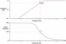
That would be the –6 dB point. So, you decide. Is dropping off maybe –4 dB at 20 Hz, the limit of audibility in humans, worth it to 'improve' or not?
⋅-⋅-⋅ Just saying, ⋅-⋅-⋅
⋅-=≡ GoatGuy ✓ ≡=-⋅
On my trancendent grounded grid there is 1 uf coupling caps.
My poweramp has 10k input impedance wich makes the combo a high pass filter.
What would be the downside to use a higher value cap?
A 10uF coupling capacitor is more suitable for a 10k load.
Last edited:
It is a bit more complicated of a calculation, but the following is more or less (i.e. good enough to draw a graph with) correct:
The 'curve' has no particular corner except the widely quoted –6 dB one. Using this formula, you can cobble together an Excel spreadsheet, with cells for R and C. Then a column of F (frequency) values of interest, and immediately to the right, a corresponding column of dB values.
As RayMa says, it is good advice to work with a 10 µF capacitor. And almost as good to use a 4.7 µF (i.e. a completely common standard value)
⋅-⋅-⋅ Just saying, ⋅-⋅-⋅
⋅-=≡ GoatGuy ✓ ≡=-⋅
R = input impedance (Ω)
F = frequency (Hz)
C = cacitance (Farads)
dB = 20 × log10( R / (R + 1/(2πFC)) )
F = frequency (Hz)
C = cacitance (Farads)
dB = 20 × log10( R / (R + 1/(2πFC)) )
The 'curve' has no particular corner except the widely quoted –6 dB one. Using this formula, you can cobble together an Excel spreadsheet, with cells for R and C. Then a column of F (frequency) values of interest, and immediately to the right, a corresponding column of dB values.
As RayMa says, it is good advice to work with a 10 µF capacitor. And almost as good to use a 4.7 µF (i.e. a completely common standard value)
⋅-⋅-⋅ Just saying, ⋅-⋅-⋅
⋅-=≡ GoatGuy ✓ ≡=-⋅
Yes, if it were a solid state preamp, a 10uF output coupling capacitor would be standard. But a tube preamp
would typically be used with a high impedance tube power amp, so the 1uF would be more normal.
However, there's some question whether this preamp can drive a 10k load with low distortion regardless.
would typically be used with a high impedance tube power amp, so the 1uF would be more normal.
However, there's some question whether this preamp can drive a 10k load with low distortion regardless.
it has an output impedance of 250 ohm so it should be able drive it. maybe not optimal, but my budget is not allowing much else.
if I change to 4.7 ore 10 uf can I risk the chance of some phase issues ore some other problem?
if I change to 4.7 ore 10 uf can I risk the chance of some phase issues ore some other problem?
Circuits can have a very low small-signal output impedance, but still be unable to drive
a low impedance load at low distortion.
A larger output coupling capacitor will certainly cause low frequency phase changes,
and for the better (more linear phase).
a low impedance load at low distortion.
A larger output coupling capacitor will certainly cause low frequency phase changes,
and for the better (more linear phase).
I don't know where al these equations come from, but the -3dB low frequency roll-off point is f= 1/(2.pi.R.C) .
For 10k and 1uF, that brings it to approx 15.9Hz. It's 3dB down at that frequency compared to, say, 1kHz.
Jan
For 10k and 1uF, that brings it to approx 15.9Hz. It's 3dB down at that frequency compared to, say, 1kHz.
Jan
A single RC coupling has a single pole, 6dB/Octave slope (for frequencies well below the -3dB point).
(About - 9dB at 10Hz)
Another factor to consider is the -1dB frequency.
If an RC coupling is -3 dB at 20Hz, then it is -1dB at 40Hz.
So first calculate the -3dB frequency, and then consider if you will accept the resultant -1dB frequency.
Example, for an amplifier system that does not use negative feedback:
If the preamp is -1dB at 20Hz, and the power amplifier RC coupling is -1dB at 20Hz, and the amplifier output transformer is -1dB at 20Hz, then . . .
That amplifier chain is -3dB at 20Hz.
Last edited:
Ooops,
My post # 13 did not make it clear.
An RC coupling with -3dB @ 20Hz:
-1dB at 40Hz
and . . .
-9dB at 10Hz (I gave this value, without stating the -3 dB frequency of 20Hz)
My post # 13 did not make it clear.
An RC coupling with -3dB @ 20Hz:
-1dB at 40Hz
and . . .
-9dB at 10Hz (I gave this value, without stating the -3 dB frequency of 20Hz)
Yes, I thought 1/(2*pi*r*c) gave us the -3dB frequency.For 10k and 1uF, that brings it to approx 15.9Hz. It's 3dB down at that frequency compared to, say, 1kHz.
That's an understatement. Confused the hell out of me. Knowing what the -1dB point is compared to it's -3dB is a bit academic surely as any change in actual amplitude between these frequencies (16hz - 40hz) is very small and liable to obfuscate the issue.My post # 13 did not make it clear.
To answer the OP's question in simple terms, changing the coupling cap unless to something mad like a 330p won't make much difference to what you hear. At these low frequencies you get diminishing returns; a 100u cap in place of a 1u won't give 100 times better bass response.
A 16 Hz hi-pass at a *Tube* amp input is fine, for three main reasons:
1) output transformers are not happy with very low frequencies.
2) normal speakers do not reproduce 20Hz and below very well ... if at all.
3) in any case, there is not much Musical Program down there ... if at all.
1) output transformers are not happy with very low frequencies.
2) normal speakers do not reproduce 20Hz and below very well ... if at all.
3) in any case, there is not much Musical Program down there ... if at all.
For the sake of flatness of frequency response low to 20Hz, I would use 10uf to couple 10K input impedance, instead 1uf.
True,
A 10k and 10uF high pass 1 pole filter is extremely flat (way beyond necessary) all the way down to 20Hz (and beyond).
10k and 10uF:
-3dB @ 1.59Hz
And the same 10k and 10uF:
-1dB @ 3.18Hz (will pass 89% of the voltage amplitude of the typical warp frequency of an LP record)
That may be a problem for most Hi Fi systems . . .
Amplifier struggling with the subsonic record warp signal.
Woofer voice coil moving so far that most of the turns are out of the magnetic gap.
A "Whoosh" sound from some loudspeaker reflex ports.
A 16 Hz hi-pass at a *Tube* amp input is fine, for three main reasons:
1) output transformers are not happy with very low frequencies.
2) normal speakers do not reproduce 20Hz and below very well ... if at all.
3) in any case, there is not much Musical Program down there ... if at all.
100%
- Home
- Amplifiers
- Tubes / Valves
- Coupling caps