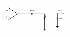
I am looking at an amp's input circuit that has coupling caps going from the input op amp to the wire that leads to the level pot, which I understand, as well as one on the return wire coming from the pot going to the next stage. Why would it need the second cap? Surely the first cap would eliminate any DC coming from the output of the op amp. The pot is connected via 18" of unshielded 22AWG twisted pair with no bypass caps on either end.
Put a voltmeter across the caps and see if there is a dc voltage there.
I figured that already. There is none on the second. The first has a few mV.
I figured that already. There is none on the second. The first has a few mV.
In that case they probably arent required.
What does the rest of the circuit to the right look like? There may be something feeding dc back to the volume control that would upset things.
Even a tiny amount of DC on the pot would make the volume/level control very nosiy when adjusting... So it must block a small amount to DC....
Even a tiny amount of DC on the pot would make the volume/level control very nosiy when adjusting... So it must block a small amount to DC....
Hi,
Would that imply the cap on the right hand side will be needed to have clean signal going into the volume?
From the second cap, a voltage divider leads to the +'ve input of another op amp. No measured DC but that might not always be the case I guess. I could see it if there was a feedback loop attached to it but there is not.
Virtually all amplifier inputs have an input offset voltage. This voltage must be isolated/blocked from passing across the wiper/track junction.
I had another look at the second cap and there does appear to be a very small (0.4mV) DC offset across the cap. This was near the limit of the meter's range (time for a new meter!) so I guess I didn't capture it first time. Thanks for all the help.
- Status
- Not open for further replies.
- Home
- Amplifiers
- Solid State
- Coupling caps on long wires
