Hi, im building a DDDac1543. Its going to a preamp with 50k input impedanc. What is the smalest output cap I can use on the dac and not loose any bass? Im looking at Solen film/foil teflon to use in dac, Im a fan of V-cap ODAM but have them as output cap in preamp and in crossover so think that is good for now. I also before have bypassed caps in signal way but dont do that anymore, dont like “smearing” of the sound, but that is just my experiance. Frank

Don't think of "smallest possible" but take some margins into account. Your preamp could be 42 kOhm in reality... Please add at least 20% margin for correct dimensioning/design. In your case I would calculate with 25 kOhm as there very likely is some stuff in parallel to that volume controller. If you have a schematic you could calculate input impedance in the various volume settings (just in case) like 9 o'clock, 12 o' clock. Wrong is to assume matters and ending up with easily avoidable errors. So calculate "worst case". If the cap is somewhat too large in reality there will be no detrimental effect. In real life one changes preamps and preamp B might be 25 kOhm and not the 50 kOhm preamp A was.
That is 1/(2 x pi x R x C) for the -3 dB point which I suggest to be 10 Herz. Don't worry about fancy brand names and dielectric types but first get the value right as that is correct engineering. You are better served with the right value Wima MKS than with a too small chosen Duelund Obbligato Gold Silver sprinkled teflon foil hand made capacitor.
And ... the best cap is no cap. DC coupling often is more difficult to realise but in many cases it is cheaper than buying boutique stuff from an always smiling dealer. People that like to be busy with cap types often don't see that they have 2 caps in series at various spots in their chain! This halves their effective value and it is twice as costly making the smile of the dealer even larger.
Now while I think the basics should be known there is an excellent online tool to calculate values: http://sim.okawa-denshi.jp/en/CRhikeisan.htm
Make sure to fill in "25k" and for example "2.2u"
Last edited:
But in reality, you may actually want smaller to roll off the bass sooner unless it is a special effects HT sub. For music, you might move your pole up a bit depending on how your speakers integrate with room gain. With DIY you can do things that in off the shelf might need an additional crossover. My main amp I changed the input cap and feedback cap for a 30 Hz pole. Pay attention to what Jean-Paul said about caps in series.
In theory things should be flat from 20 Hz to 20 kHz when adhering to the good old HiFi DIN norms that never fail on you. Therefor one can not go wrong with 10 Hz as -3 db point. The point of the caps is to block DC (0 Hz) to oversimplify a little. In practice I see randomly chosen expensive caps and roll off issues more than I like (not to mention absurd amounts of totally useless GAIN). Many seem to design by just "doing something" which is sad really. This often involves calculating best case which simply does not work optimally as things are not ideal.
Yes the 2 caps in series issue occurs a lot. For example a source like this DDDac1543 with output caps connected to a preamp that has input caps both before and after the volume potentiometer (3 caps in series, it happens) 😀 It then makes sense to investigate some time in the structure of possible other sources and when all sources have output caps to simply omit the first input caps of the preamplifier. Beware that some preamps can have serious DC offset at the inputs like some tube devices. Always check matters before changing anything.
Yes the 2 caps in series issue occurs a lot. For example a source like this DDDac1543 with output caps connected to a preamp that has input caps both before and after the volume potentiometer (3 caps in series, it happens) 😀 It then makes sense to investigate some time in the structure of possible other sources and when all sources have output caps to simply omit the first input caps of the preamplifier. Beware that some preamps can have serious DC offset at the inputs like some tube devices. Always check matters before changing anything.
Last edited:
Hi again, after the dac I have Pass B1 Buffer with 10uf input capacitor, 50k atteunator and 2.2 uf output capacitor ( : The B1 stays in the system. So with that information can you guide me withh the output cap for the dac? I look at the formula but can not wrap my minde around it ( I will get it one day ). Frank
Nothing changes. Use the formula and calculate worst case. The Japanese online filter calculator always works OK but I will tell you the value if it is too much. What would be a good choice is to use the DCB1/Mezmerize/Pass B1 R2 that all have no coupling caps at all. Saves 2 caps per channel* with better sound as a bonus.
The standard B1 has asymmetric PSU so it needs input and output caps which are 1 µF input caps and 10 µF output caps. In your case you indeed have a few caps too many (wonderful) in the wrong values (WHY?) but that is unavoidable with a device that has an asymmetric PSU. This is called "system choice" and could be better. Normally one tries to avoid too much caps in the signal path as they are not the most ideal of components and they're large and expensive. It it "stays in the system" with aforementioned plain wrong value input and output caps you have a self created/chosen built in defect and you are a respected customer at the local boutique cap dealer 🙂 A technical suggestion is to correct the mistake and swap input and output caps. Small change, high gains and 100% free.
Both B1 and DCB1 have an optimal potentiometer value of 25 kOhm. So the suggestion is to use a 1 µF 50V (minimum) film cap of boutique choice as minimum value. A 2.2 µF won't hurt.
* Please think of what the output cap of the B1 is connected to in the power amplifier. Yes again a capacitor.....System choices tend to follow up at various spots...
Last edited:
I may remember wrong, that the 2,2uFis 1,0uF, and yes its the other way around. 10 on output ( mixing up stuff here, hade a B1 Nutube for some time ). The B1 was 25K, but think Nelson change that to 50K some time.
And amps also tend to have it on input. I have Hiraga 30w and Dynamic Precision 6.1 as amps, not sure about them, think maby the DP has servo at input. I also have a Accphase F20 between pre and power, so many parts in the chain.
You don't give exact answers that would help me to help you. You have enough information to chew on and you are able to calculate the correct value of coupling caps, just practice the formula a few times with randomly chosen values and understand how the mechanism of high pass filters works. The amps and other devices you are not sure about can be looked at by yourself to make sure what the situation is regarding coupling caps. Having many coupling caps is not exactly a benefit.
It should be clear by now that you are best off with a DC coupled preamp/buffer as your source and power amplifiers have caps. Even if the devices after the preamp wouldn't all have input caps the situation still would be better DC coupled as offset of, for example, a DCB1 is below 1 mV.
It should be clear by now that you are best off with a DC coupled preamp/buffer as your source and power amplifiers have caps. Even if the devices after the preamp wouldn't all have input caps the situation still would be better DC coupled as offset of, for example, a DCB1 is below 1 mV.
Last edited:
Ok, tanks for answer. I will practice on the formula. Not that easy for an newbe in electronics, Im just a welder ( : Frank
Make it simpler then. If you use 25 kOhm as load then Fc = 1(2 x pi x R x C) can be written as 1/(157050 x C). You want the outcome to be around 10 Hz. Now there is only 1 variable and that is the cap.... A V-cap ODAM of course 🙂 -> with a 2.2 µF cap this is 1/(157050 x 0.0000022). Fc = 1/0.34551 = 3 Hz. The formula uses resistance in Ohms and capacitance in Farad not µF. This makes the - 3dB point around 3 Hz. That is fine with modern source devices. However in some cap loving circles the mantra is that large caps are worse sounding than small caps (never say the terrible words that the best cap is no cap!). There is some truth in that at the extreme side of things like 100 µF film caps but even if it would be slightly suboptimal it still is way better than randomly chosen too small caps that indeed lead to low roll off.
If you are worried that a 2.2 µF V-cap ODAM sounds worse than a 1 µF version then recalculate the - 3 dB point with 1 µF. Simple. If it is still below/around 10 Hz it is also fine.
Trick/tip: if any of the devices one has is for example 10 kOhm then it makes sense to adjust the previous device (preamp) to a 10 kOhm load. Then you have guaranteed results with all devices regardless if they're 10 or 50 kOhm. Nothing worse than the tube world practice of needing to "marry" devices with eachother.
Last edited:
?
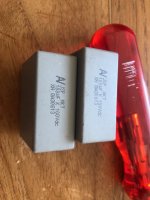
Frank, could you do me a favor and calculate if I have around 10 Hz cutoff frequency when using the caps on the picture with a worst case 100 Ohm load? And what about the normal load of 220 Ohm?
Frank, could you do me a favor and calculate if I have around 10 Hz cutoff frequency when using the caps on the picture with a worst case 100 Ohm load? And what about the normal load of 220 Ohm?
Attachments
Last edited:
May I kindly suggest to write electrical stuff correctly? So Hz, Ohm, µF, V, A etc.
No that is a wrong answer as 1/0.0625 = 16 Hz. The online calculator is your friend. Make sure you write "100" and later on "220" for the Ohms and "100u" for the cap. The app otherwise does not work correctly. It needs exactly the right names for correct calculation. When using larger value resistance that will be "25k" and with smaller capacitance values for instance "100p".
http://sim.okawa-denshi.jp/en/CRhikeisan.htm
Last edited:
Ok, so you put the Fc in the app. I see, and I will learn the Hz and Ohm. Now I can practice, ihaaaaa!!
NO. The app tells you the Fc as an outcome among other things that are over your head for sure. The Fc is the results of the load resistance and the coupling cap. If it is not clear yet... the larger the cap AND/OR the higher the load resistance -> the lower the Fc....
Or the other way around ... just think if your ears will be happy when the Fc is 200 Hz. Will you experience that deep bass?!
Or the other way around ... just think if your ears will be happy when the Fc is 200 Hz. Will you experience that deep bass?!
Yes it is enough for today. Exercise a few calculations manually and verify with the online tool. You'll experience that many mistakes occur translating pF, nF, µF manually to the required F value. For this one really needs to use exponents. The app is flawless but knowing to do it manually is true knowledge.
You'll also notice that you now will know how to do stuff correctly which is a big personal gain. You will also notice incorrect mating of the devices you and others have and you will be able to correct to a well working situation.
Now next level is the low pass filter as should be at inputs of (pre) amplifiers. http://sim.okawa-denshi.jp/en/CRlowkeisan.htm
Here I would suggest to use 100 kHz as - 3dB point. Now you filter out any HF/RF coming into your chain. Often forgotten but quite necessary in todays electrically polluted environment.
Last edited:
- Home
- Source & Line
- Digital Line Level
- Coupling capacitor dac.