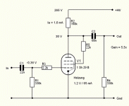
Hi fellas!
I'm having a little problem with my pre-amp (seen on the photos thread): it lacks bass.
the input cap is a 22nF and the output one is 68nF(or is it 680? it appears marked .68...)
Could i ommit them or if not, what value should they be?
Thank you very much,
Francisco
I'm having a little problem with my pre-amp (seen on the photos thread): it lacks bass.
the input cap is a 22nF and the output one is 68nF(or is it 680? it appears marked .68...)
Could i ommit them or if not, what value should they be?
Thank you very much,
Francisco
Attachments
The input as it is in the diagram has a -3db point at 20hz, this is too high in my opinion, tripple size of the cap and and the -3db point will be at 5hz.
The output cap depends on the amplifiers input impeadance, lets say bad case senario of a 10k input power amp, the the output cap will have a -3db point at 234hz really bad.
If you do'nt have a power amp hooked up the output cap sees the 330k resistor only then the -3db point will be 7hz which is good but as soon as you hook up a power amp the 330k changes to what ever the the parralel of the 330k and the power amps input impeadace is and the bad case that i calculated was the 10k this is not acceptable.
So the cap for 10k will have to be 4.7uf which will be good for nearly 100% of the poweramps out there.
Cheers George
The output cap forms a voltage divider with the load. If the load impedance is R and the coupling cap is C, the response will be down 3 dB at f = 1/(6.28*R*C).
Simpleton the maths for the -3db piont are
2Pi x the resistance x by the capacitance 1/x = the -3db piont
Cheers George
2Pi x the resistance x by the capacitance 1/x = the -3db piont
Cheers George
Another point often neglected is that the output impedance rises dramatically with small caps. In georgehifi's example it's literally 10 kohm at 234 Hz. Un- or poorly shielded interconnects need not apply. I found very small caps resulted in increased susceptibility to RF interference even when used as input caps in a shielded chassis.
Another overlooked point-
The stage is using grid leak bias. When the bias is very low the input grid of the tube does not look like the ideal open circuit anymore. The input impedance of the grid is low enough that the lf performance of the input side of the tube is worse than the calculations would have you think.
Gary
The stage is using grid leak bias. When the bias is very low the input grid of the tube does not look like the ideal open circuit anymore. The input impedance of the grid is low enough that the lf performance of the input side of the tube is worse than the calculations would have you think.
Gary
So...what should i do then? (if accompanied with explanations, i would appreciatte, i wanna learn a bit😀)
Thank you all very much
 (if accompanied with explanations, i would appreciatte, i wanna learn a bit😀)
Thank you all very much
Use a 4.7uF cap for your input. Even with the grid leak bias (nice catch, Gary, I missed that one!), your f3 will be low enough. And then you can start worrying about the next problem you'll have with this circuit, the high output impedance.
Simpleton said:So...what should i do then?(if accompanied with explanations, i would appreciatte, i wanna learn a bit😀)
Thank you all very much
Just put a 4.7uf Solen on the input
And a 15uf Solen on the output.
You'll be right.
Cheers George
4,7uF on the input and 10+4,7uF on the output.
Had it connected today in my car's subwoofer amp (low-pass at around 200Hz) playing a compiled CD with 5 to 400 Hz sine wave tracks, and it goes down to 10Hz (well it plays the 5Hz signal, but 10Hz seems to have a bit more "strenght")!
Too bad it hums a bit, but it's only audible very close to the speaker ...
Thank you!!!!😀
- Status
- Not open for further replies.
- Home
- Amplifiers
- Tubes / Valves
- Coupling cap question
