Thank you very much, I'll try to get some things ordered! 🙂
I got to thinking here, I'm not sure how the input stage works on the DSP but could this be a problem there.
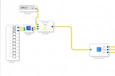
I'll insert a picture of how the program looks there to show what I mean.
What I'm thinking of is that on "Slew control" for the volume I never get 0 level/output. There's always some sound (music) coming from the speakers, and I haven't really thought too much about it as if I'm playing music I do, so who cares.
But on the input where I use the two ADC with/for source select, instead of Left/Right channel, if the Slew control doesn't go to 0 on the channel that's supposed to be muted couldn't that create a problem/interference/oscillation? (as it's also poorly shielded)
Then again, I can't really hear anything when I flip the switch and don't have any audio on the other input channel...
Maybe add some mute function..?
I don't know, it feels like I'm missing something obvious here, the moduls is supposed to be pretty much plug and play, I would think. lol

Not sure about what the slew control is supposed to be doing. A slew limiter is not the same as a volume control. Slew is the 'rate of change over time' of a signal. Digital volume controls may need to be slew limited to prevent 'zipper noise' when the volume level is changed too fast. So, if 'slew' as shown in SigmaStudio window is a property of a volume control block, then it should not be zero. It should be high enough to allow the volume to change without causing switching noises if the volume is changed quickly.
It's just Xfade with a slew here, I'm using it as source select between the two analog inputs to the board.
The volume control with slew I use is the regular one, I believe there's only one that can be used when you use outside analog control, if I recall correctly.
I can see how it might be different from what I'm used to in analog equipment (amp/volume), that you would use something else to completely mute the output. Though my concern for problem here is regarding the input. 🙂
Well it just got me thinking about different paths for the signal to go, some possible sensitivity around that area when I moved around cables (believe it was the power cord).
And I'm not sure if the wires are the best (pretty un-insulated), or wired the best way. I have 1 signal ground in on 1 DSP-board, so I wired the two RCA grounds belonging to the same DSP with one wire, but I didn't ground the two RCA-connector groups together.
So signal ground to the two DSP-boards isn't connected, by wires.
I began to look at the paper for the power supplies, as they have Aux-power I figured that I could try and use it to power the DSP boards instead of the amp's Aux-power. But it said something about that it's not well regulated, so maybe I'm opening up another can of worms for no good reason.
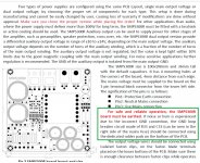
I did however see that the 300W unit "should use earth", "hum can be a problem", and there's a soldering patch to use on the bottom of the board otherwise.
Could it all be that easy?? (Well, easy found, I'm not going to change all the wiring in my house)
I highlighted the section in green in the picture.

The volume control with slew I use is the regular one, I believe there's only one that can be used when you use outside analog control, if I recall correctly.

I can see how it might be different from what I'm used to in analog equipment (amp/volume), that you would use something else to completely mute the output. Though my concern for problem here is regarding the input. 🙂
Well it just got me thinking about different paths for the signal to go, some possible sensitivity around that area when I moved around cables (believe it was the power cord).
And I'm not sure if the wires are the best (pretty un-insulated), or wired the best way. I have 1 signal ground in on 1 DSP-board, so I wired the two RCA grounds belonging to the same DSP with one wire, but I didn't ground the two RCA-connector groups together.
So signal ground to the two DSP-boards isn't connected, by wires.
I began to look at the paper for the power supplies, as they have Aux-power I figured that I could try and use it to power the DSP boards instead of the amp's Aux-power. But it said something about that it's not well regulated, so maybe I'm opening up another can of worms for no good reason.
I did however see that the 300W unit "should use earth", "hum can be a problem", and there's a soldering patch to use on the bottom of the board otherwise.
Could it all be that easy?? (Well, easy found, I'm not going to change all the wiring in my house)
I highlighted the section in green in the picture.

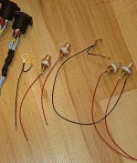
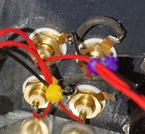
Maybe you could post a pic of the wiring? When moving wiring around has audible effects, that's already a problem that needs fixing.
Also, it could be that the solder patch for a 'hum-breaker' on the bottom of the board is worth trying.
Its not uncommon for audio components connected together to form an overall system to have ground loop problems. Sometimes the owner doesn't even realize there is a problem until it is fixed and the sound quality gets better.
I'll post a couple of pictures, but I should warn that some of you might get nightmares. 😀
The soldering is well conducting, but that's it, my hands isn't stable enough for anything fancy looking. And I changed the short wire between the floor picture and the installed one, it was too stiff and thin.
The humming came sometime when I moved the power cord in that area, so not when I move the cables themselves.
I had planed on making a steel cover for the wiring, as EMI shield, but figured I could try first and maybe get better wiring instead.
I'm trained in electronics in cars, doing engine analysis with oscilloscope etc, I have very little experience with this kind of work. That's why I installed everything on a aluminum sheet, with my background I thought that as much ground as possible would be best. But I'm beginning to see now that there's a bit more to it here. lol
I also looked at different oscilloscopes, there are some fairly cheap to buy, but I'm not sure how good they are.
Any recommendations, for the bare minimum? 🙂


Signal wires should be very short length, coaxial with ground shield, or else twisted signal and ground pairs. Otherwise signal wires can act like antennas and pick up noise.
I braided these, but maybe that doesn't work like twisting? 😕
Very stiff insulation on these so twisting might be difficult. I'll order a piece of shielded wire so I can stop worrying over that, I searched harder now and found one with two signal and one ground.
I'm going to go over the other wiring as well, I used some rather stiff power wires for one amp and they don't cooperate too well in the tight space.
Before I go ahead and solder that patch on the power supply, in layman's terms, what are the possible drawbacks?
I'm guessing it's changing how it's grounding to the screws/chassi, opening up a circuit to/for something... I guess I still have a hard time to understand that you don't want everything grounded in every possible way. lol
I got the new tweeter today, I will try my best now to not let any magic smoke escape it. 😀
Thank you! 🙂
I will take some time and read up during the weekend, maybe refine some of the mechanics, and do a quick test. I'm out of funds for now, but got time on the other hand. lol
I will take some time and read up during the weekend, maybe refine some of the mechanics, and do a quick test. I'm out of funds for now, but got time on the other hand. lol
I've been going through the papers little by little here, still have some left to read. But I have corrected some mistakes, like the "Pin 1", that I apparently had made. Cleaned up some other things with the wires (still some left), like twisting the balanced cables instead of braiding as I removed the ground, shortened the power cables from the PSU, and... probably something else as well.
I played briefly now and it seems like the muddy sound is gone, sounds louder and more clear.
But I still got a buzz, and I would guess it's in the 50hz region. Came mostly from the tweeter, midrange though. (I didn't spend any length of time to listen to it exactly, for obvious reasons)
So I still have some problems to find, but it seems to be going in the right direction.
The only cables left that could cause problems is the unbalanced input, I think. But I'm guessing that's magnetic radiation in that case.
After that I'm guessing I have to lift the boards so that they only are electrically connected by the cables. 😕 The DSP units are a bit erratic in their volume control, so I'm guessing that's a good place to start, they might be "complaining" about bad currents.
Couldn't find a soldering point on the PSU by the way, but did find the components.
CD player and amplifier is connected at the same socket, CD player goes through a small extension cord though. From what I read I guess it's relatively okay as none of them are grounded.
I guess that was all for now. 🙂
I found an article about DC offset and decided to see what I got, and here's the numbers on the amplifiers output:
3251:
1: 16,8mV
2: 16,7mV
3: 4mV
4: 22,8mV
3255:
1: 1,0mV
2: 2,2mV
I measured over the negative low level input to the DSP to see if I could find anything (ground to chassi).
1: 2,2-4mV (oscillations)
2: 6,8mV
Number 2, the high number, is the shortest cable of the two. I decided to try and connect the RCA connectors and wires that was supplied with the DSP and route them over the edge away from other electronics (if it was a magnetic field), but there was no change in the reading at all (6,8mV).
I disconnected the (12V DC) power cable from the Amplifiers to the DSP and did the same measuring (The rest was powered On).
1: 0,8mV
2: 1-4mV
But my multimeter has been through a lot and is a cheap model.
So from what I have learned so far (please correct me if I'm wrong) a DC offset from the amplifier could be the reason why the cap didn't save my tweeter, but the voltage I see now isn't really at that danger level.
I also read about extreme oscillations at a very high frequency, something the caps might not help with either, but I'm guessing that was when my PC was connected, in that case...
But the again, something must have killed the audio output when it passed through the cap, while still providing enough power to do damage... 😕
I'm going to continue and educate myself on the subject and try things, I feel both more confused and educated each day. lol
- Home
- Source & Line
- Digital Line Level
- Could this be a digital line level problem?