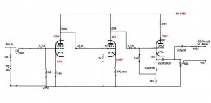
Could someone look at my circuit if there is something not right about it?
It's a stereo preamp (one channel shown) which also serves as a low gain mic preamp. I've build it years ego but did some minor changes and also changed the output from anode to cathode so I can connect it to heavier loads like solid state mixer without worrying about over loading the output. Thanks for any info.
Also, I thought about implementing NFB but didn't bother because it would lower the all ready fairly low gain for mic, but would it be worth the trouble anyway?
An externally hosted image should be here but it was not working when we last tested it.
Attachments
Last edited:
If you would like some more gain, use active loads. They can also deliver lower output Z than the 12AU7 cathode follower. Use them on both 12AX7 stages and you will avoid the high-frequency roll-off on the first stage.
cheers,
Douglas
cheers,
Douglas
Umm… wait!If you would like some more gain, use active loads. They can also deliver lower output Z than the 12AU7 cathode follower. Use them on both 12AX7 stages and you will avoid the high-frequency roll-off on the first stage. cheers, Douglas
I think just the opposite is true: the higher the gain of a triode stage, the greater Miller capacitance squashes high frequency response. The ideal 'opposite case' is the cascode topology with the anode of the 'amplifying' triode held at near-constant voltage, turning it into a current modulating device. Miller-capacitance HF attenuation is so low that garden variety triodes can amplify RF up to several tens of megahertz!
So, no. I don't agree with the recommendation.
________________________________________
Recommendations
(1) Grid-stopper resistors — 680 Ω to 2,200 Ω, soldered at-or-very-close to grid pin
(2) Cascode front end — stiffen the HF topology.
(3) Capacitor bypass — first stage cathode 'bias' resistor
(4) Interstage cap HF bypass — 1.0 to 3.3 nF mica or PTFE hi-volt (450+) capacitors
This adds ½ bottle per channel to implement the cascode topology. Well worth it, in my experience. If (as I would) you wish to keep the bottles separate on each channel exclusively, then the extra half-bottle (single triode) could deliver the additional mic-level gain you want, or alternately, could displace the 12AU7 output cathode follower stage. Just saying… might be a tad unusual, but 12AX7 in relatively high output impedance buffering isn't a bad valve. Especially if № 1 is done.
Alternately, instead of a ½ 12AX7 to implement cascode, one could just as easily and effectively use a yuck-pew-pew-choke-bleh grain of sand to be the cascode 'anode buffer' for the first stage 12AX7. No extra bottles, no extra holes to cut in chassis. Plenty of HV-safe MOSFETs to choose from, or if you're into older-school (and arguably more robust) bipolar sandy grits, then a ( https://www.mouser.com/datasheet/2/115/ZTX600-92901.pdf ) would do quite nicely. 87¢, quantity 1. No filament.
№ 3 delivers greater gain without substantially compromising linearity, at stage 1. I would not use capacitor bypassing of the cathode resistor on stage 2.
№ 4 addresses normal small-can interstage capacitor (perceived) HF signal impedance issues. I used to prefer mica, but that was when they were ubiquitous and pretty cheap. Now, they're not. PTFE ('teflon') is an excellent alternative, especially in nanofarad values. Remarkable.
________________________________________
Lastly, Negative Feedback. Your circuit's topology that does not have self-bias bypass capacitors already has subtle negative feedback in play! Quite a bit, actually, as it is on 2 stages. You could opt for a 3rd gain stage, I suppose, then use its inverted (relative to incoming signal) phase as a simple enough GNFB to stage 1. Or, for that, without the additional gain stage (which likely would be needed to make up for lost overall gain), if gain were already fine, then injecting a bit of stage 2's anode signal back into stage 1's cathode bias would deliver higher linearity overall. But at the expense of gain, as always.
In quite a few amplifiers I've designed, my choice is a nifty little DPDT (center off!) switch that can switch in either of 2 capacitor bypasses, or none. The 2nd pole tho' is not what you might think it is! Instead, it also switches in a modest signal attenuator to compensate for the added gain coming from the capacitor bypass. Not to squash ALL the gain, but to tame the rather large increase in gain nominally incurred.
This last bit tho' is kind of subjective. Hence why I use the 3-position DPDT. 'Down' is bypass capacitor with compensating attenuation, to where overall gain change is near 0 ΔdB. 'Up' is a different bypass capacitor, without attenuation compensation, resulting in a +10 ΔdB or greater additional gain. 'Center' is none-of-the-above.
To keep the capacitor-switching-in pop to the barest minimum, I 'leak charge' the caps with a 22 kΩ resistor across the switch. 0.1 dB 'across resistor' effect.
________________________________________
There you go, buddy. Hope it helps.
⋅-=≡ GoatGuy ✓ ≡=-⋅
Last edited:
I do not like the 50K pot at the output. I would at minimum make that a 10K pot, or leave it off all together and just use the pot at the input.
50k pot running a 3 foot shielded cable of unknown capacitance is not a good idea.
Unless you are trying to make a Low Pass Filter that is in the audio band.
Unless you are trying to make a Low Pass Filter that is in the audio band.
Well there GoatGuy, an active load can deliver a much lower output Z, and therefore drive the increased-by-Miller input capacitance. Your agreement is not needed for this to be so...🙂
cheers,
Douglas
cheers,
Douglas
I would move the 50K output pot from the output of the cathode follower to the input of the follower. Unless you have plan to add NFB later on.
Well there GoatGuy, an active load can deliver a much lower output Z, and therefore drive the increased-by-Miller input capacitance. Your agreement is not needed for this to be so…🙂
cheers,
Douglas
Hey there, Doug. Good hearing back from you.
Could you either show (link to / upload) a schematic, or something concrete? I tend not to understand what people are talking about unless I see a supporting circuit diagram.
I know, its something about being born before the gods invented Dirt … but still …
Thanks in advance,
⋅-=≡ GoatGuy ✓ ≡=-⋅
GoatGuy,
Yes, I want to see that circuit from Doug too.
Perhaps he was referring to an SRPP circuit, and pulling the output off of the cathode of the top tube in the SRPP stack.
Yes, I want to see that circuit from Doug too.
Perhaps he was referring to an SRPP circuit, and pulling the output off of the cathode of the top tube in the SRPP stack.
That's a lot for the input, sorry I'm a bit late with the reply.
Just a few points to replies here. Regarding increasing the gain, I don't need anymore for the mic, it has enough gain from close range mic application so that's all I need. As and audio preamp it is fine, totally quiet with gain to spare.
I didn't realize that not having bypass cap creates NFB. Thanks for that, that's handy to know.
About the grid stoppers - I've opted not to put them in at the time, figuring the input 100k should be enough to stop any stray radio frequencies noise from outside. I also didn't want to loose any HF, degrading the original signal. Not sure if there would be any audible difference but that's what I did. I get no radio frequencies or anything, it is quiet.
Lastly regarding the 50K output pot most of you don't like. I have to have a pot there so when I crank up the input to the max (if I want to distort the preamp), so I can control the high output going to the mixer. I've chosen 50K because I didn't want a heavy load on the cathode because sometimes I'd connect the to "mic in" on mixer those have quiet high load.
Basically I tried to avoid output distortion. That was just my theory. I'm not sure what would work better on output.
But I'm kind of glad to none of you have mentioned some major fault that would make it unsuitable for audio preamp sound quality. That was my main concern. I'd hate to be using something and later find there was a problem with the sound. It happened to me many years ego where I've build similar preamp, spend six months recording,only to realize that the unpleasent sound I was getting, was from my own build preamp and not some other cheap gear I used with it. It was one of these things that only showed up when I recorded many tracks, only than I coud hear that something doesn't sit right with the overall sound but couldn't put finger on it. If I remember correctly, I had 12AX7 on the output and running either from cathode or anode trough a cap straight out. Now I think that maybe the unpleasant sound (same type of distortion) could have been the 12AX7 being simply loaded too heavy when connected to SS gear like mixer.
Last edited:
Could someone look at my circuit if there is something not right about it?
The voltages indicated around the first stage are slightly off when checked with Ohm's Law. It will work but i think it is better to use a cathode resistor of 1K8 so you wil get a slightly higher Vg (see Philips datasheets for the ECC83).
The second stage can't be right. The 12AX7 will surely not pass 3 mA at Vak = 80 V and Vg = - 2.25 V. With Vak = 80 V and Vg = -2.25 V a 12AX7 would practically be in cut-off mode (no current flowing).
In the third stage the 12AU7 passes 5 to 5.5 mA according to the voltages indicated in your schematic. So Vg must be -1.33 V (V= I x R = 0.0049 x 270 = 1.33) to -1.5 V. The datasheet for the 12AU7 gives about 8 mA at Vak = 95 V and Vg = -1.33 and about 7 mA at Vak = 95 V and Vg = -1.5 V. So something is not right here.
I think you should run the 12AU7 at a somewhat higher value for Vg because of possible gridcurrent. So i think the resistor of 270 Ohm should be higher.
Last edited:
- Home
- Amplifiers
- Tubes / Valves
- Could someone check my circuit?