Hi All, been installing an Audison F8.9 DSP/Amp into a car and had to tap into the output/speaker cables of the OEM amp, to feed to the DSP, and all went well until replacing the factory OEM speakers, when i realised the wiring was different colours at the speakers compared to what i had tapped into at the OEM Amp side.
I had the negative battery terminal removed, and the speaker output plug removed from the OEM amp, and checked continuity between the speaker wires at the doors and the wires i had tapped into at the OEM amp side, to establish what colours at the OEM amp side were connected to what colours at the OEM speaker end.
However i was getting some strange readings, as was getting continuity tones from more than one set of speaker wires, and then i realised that I still had the speaker output cables plug leading from the DSP/amp still connected, i therefore removed that and all was fine with continuity as you would expect, with continuity only on one wire at the speaker and one wire at the OEM amp side, therefore it must have been the DSP internal circuity that was causing the strange readings/continuity on more than one set of speaker wires.
Anyway, my question is, even though i was checking continuity between the speaker wires at the OEM amp side and door speaker wires, because i still had the speaker output plug connected at the DSP/Amp, could i have blown a channel whilst checking continuity on those speaker wire outputs whilst they were still connected to the DSP? As essentially i've sent voltage up the output line?
Hi Perry, it's difficult to tell, there is sound coming out of the channel but it's a Centre Channel and therefore only one speaker, it sounds a little lower in volume than the front tweeters and also a little muffled when isolated, but then all the speakers sound a little muffled when played in isolation.....
Will I blow anything if use a multi meter on the end of each pair of positive and negative speaker cables to compare all channels?
Will I blow anything if use a multi meter on the end of each pair of positive and negative speaker cables to compare all channels?
Hi mate yes I have esured all the positive and negatives are correct with pos to pos and neg to neg, I found the exact wiring diagram for my car online showing the wire colours and wiring plugs/pin no's coming out of the oem amp, and also the reason I'm worried about blowing a channel is because when I took the drivers door panel off and removed that speaker, the wiring colours were red and black and were different colours than that at the OEM amplifier output side that I connected to, and even though I was quite sure red would be pos and black neg, I tested for continuity between the two to confirm, but also tested with other wires whilst connected to the dsp unit (with battery negative removed) hence why I'm concerned.
Using the meter on ohms or volts is generally safe.
Do any of the input wires for the amp/DSP read anything near 0 ohms to the RCA shields or to the non-bridging speaker terminals of the amp/DSP?
Do any of the input wires for the amp/DSP read anything near 0 ohms to the RCA shields or to the non-bridging speaker terminals of the amp/DSP?
This is the multi meter I have and it has an Ohms setting and also a buzzer option, and when turned to the buzzer it does the same as Ohms but sounds an alarm on continuity.
https://www.screwfix.com/p/lap-ac-dc-digital-multimeter-600v/161fg
My understanding is it puts a small voltage up the line to test for continuity?
Would this not blow a speaker channel output from the DSP/Amp as I tested the speaker wire whilst connected to the DSP/Amp output?
I forgot the plug was still in the DSP until I see continuity in other speaker wires that shouldn't have been connected and then realised the plug was still in the DSP..... When removed all was fine.
Continuity means nothing, specific. For one of the meters I use, the it will show continuity for anything below 25 ohms.
When in continuity, diode-check or ohms, the meter applies a very small voltage to the probes and uses that to give a reading. For diode-check and ohms, those readings tell you something. For continuity, the results are vague.
The current used for ohms or diode-check won't harm the amp (power off). It's unlikely that what's used in continuity mode is similar to the other two modes.
You haven't given any definitive information that indicates that anything is blown/damaged.
Do any of the input wires for the amp/DSP read anything near 0 ohms to the RCA shields or to the non-bridging speaker terminals of the amp/DSP?
Do any of the input wires for the amp/DSP read anything near 0 ohms to the RCA shields or to the non-bridging speaker terminals of the amp/DSP?
Hi Perry, just to clarify what your asking, I have broke into the oem amplifier at the speaker wire output block and taken the output feed from the oem amp to the DSP/Amp. It goes into the DSP via the high level speaker input wires/connector and it then comes out of the DSP/Amp via output speaker wires and returns back to near the OEM Amp and I then connect back up to the other end of the OEM speaker wires to feed the speakers via the OEM speaker cables.
Are you asking me to put the multimeter in Ohms and read between each of the 'input' speaker wires going into the DSP/amp that are coming from the OEM amp? And the other probe to where? As I don't have speaker terminals they are a wired input and output connector but I can use a crocodile clip and thin piece of wire and get into the crimps if needed...
Are you asking me to put the multimeter in Ohms and read between each of the 'input' speaker wires going into the DSP/amp that are coming from the OEM amp? And the other probe to where? As I don't have speaker terminals they are a wired input and output connector but I can use a crocodile clip and thin piece of wire and get into the crimps if needed...
The red probe would go to each input of the DSP/amp that you're taking from the OEM amp.
The black probe would go alternately from the RCA shields to a non-bridging output speaker terminal of the DSP/amp.
You can touch the meter probes to the pins in the nylon connectors on the DSP/amp (no harness plugged in).
There are some (not many) inputs to amplifiers that are essentially ground. If you connect the output of the OEM amp to an input that's essentially ground, the OEM amplifier could be damaged. That's the reason for the tests above.
While you're checking things, also measure the DC voltage on the output speaker terminals of the OEM amplifier with the amp on. All I'm looking for is whether the speaker terminals are all near 1/2 B+ (6v) or all are near 0v.
Many Thanks Perry really appreciate it, will check this weekend and report back (although I may have some questions) 😊👍
Sorry to sound a numpty Perry but I'm completely lost in what I have to do?
Could we please break it down into baby sections! 😭
Firstly I will remove the negative from the battery?
Then I remove the speaker wire output plug from the oem amp that leads to the dsp/amp (that I tapped into for the speaker wires to lead to the dsp/amp)?
Then I leave the speaker wire input plug plugged into the dsp/amp, get my multimeter and turn it to Ohms, and then I measure between the speaker input wires of the dsp/amp and the speaker wires coming out of the output plug of the dsp/amp?
Is the above correct? As you mentioned RCA shields to a non-bridging output speaker terminal of the DSP/amp.?
You're tapping off of the speaker output of the OEM head unit. In some amps, the speaker level input has grounded terminals. This is rare but has happened. I'm trying to confirm that your amp/DSP has no grounded inputs.
If removing the negative terminal isn't causing any problems (it can in some vehicles), remove it. It's not something I would normally recommend as necessary but if you've been doing this, do it here.
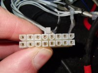
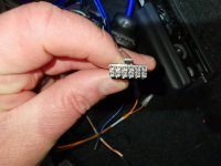
Post a photo of the nylon connectors (looking into them) on the amp/DSP.
If removing the negative terminal isn't causing any problems (it can in some vehicles), remove it. It's not something I would normally recommend as necessary but if you've been doing this, do it here.
Post a photo of the nylon connectors (looking into them) on the amp/DSP.
Hi mate please note I've tapped off the speaker output of the oem 'amplifier' not the 'headunit' as my car has a seperate oem amp in the passenger side footwell (Honda Civic 2019).
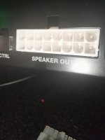
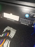
Please see attached photos showing the speaker input and output plugs at the dsp/amp end.
Please see attached photos showing the speaker input and output plugs at the dsp/amp end.
Attachments
For the output terminals, do all of the non-bridging speaker terminals read 0 ohms to the other non-bridging speaker terminals?
Hi Perry, therefore disconnect all connections on the back and I can take it to my work bench and do it? And check with meter switched to Ohms and just put the red probe on the pos terminal and the black probe on the nagative terminal and check each pair like that? And I won't blow anything by doing that?
- Home
- General Interest
- Car Audio
- Could I have blown a channel?