Hello, this is my first time posting here!
I’m thinking of installing a VVR from Ampmaker into my Vox AC4TV as I’d like to get some dirtier sounds at lower volumes. I’m not very experienced with electronics but I recently resoldered the connections on my telecaster selector switch, opening the thing up along the way, so I reckon I could put the VVR kit together without any problems. But I’m not sure if a novice like me would be able to install it in the amp itself.
I’m fairly technically minded and can follow instructions but I can’t read a circuit diagram, as yet. So I’d like to ask for advice from anyone out there who might have carried out this mod.
- How many steps are involved in the installation? I can only see three cables coming off the VVR kit - does it simply require three wires to be soldered in somewhere?
- Does anyone by any chance have something that approximates a step-by-step guide to installing this VVR with photos of the circuit board rather than a diagram?
- Is it possible to install the VVR and retain the AC4TV’s existing ‘attenuator’?
Attachments
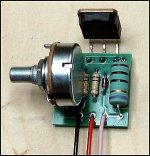
Might be a starting point for discussion.
It is three wires that you splice two of the wires into the circuit, the third goes to ground. Look at the schematic (learning experience here) there is a power transformer below the EL84 tube, there are two resistors R14, R17, in series (in line) with Q2, Q3. They join together at that dot. Next to it is the filter capacitor 100uF with its own dot (the dots are a connection point). What you would ideally want is to insert the VVR two wires in between these two points.
http://dealers.korgusa.com/svcfiles/AC4TVH_SManual.pdf

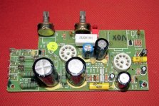
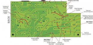
Here is the board, it is an Ebay ad so I don't know how long it will be up, save it if you can. (Anybody know how to past it permanently in this site?) On the lower left corner are the two resistors and two diodes. The resistors are the green things with the colored bands on them, the two diodes are black and have a bans on one side. Ideally you want to put the one wire where these two diodes join and to one side of the capacitor, the next part to the right of it.
The problem is the it would require some surgery, cutting the trace between the diodes and the capacitor. Not too friendly a layout even for a tech. There is another option, not one usually done. Back to the schematic above, Between the 1000 uF capacitor and the 33 uF capacitor is a 470 ohm resistor. In the picture below it is in between the two capacitors under the tube socket. You could unsolder one end of the resistor, put one of the wires in the hole and solder the other wire to the resistor. The ground wire to a ground point again. The resistor should be supported rather than hanging from one lead so maybe a dab of silicone to the board could do. The end with the wire soldered to it should be insulated with a piece of heat shrink tubing.
What the VVR does in this position is that it does not attenuate the whole amp but does do the EL84 screen and the preamp. Lowering the screen voltage makes the tube less sensitive and you end up turning the preamp more. I don't know if you would get the same sound as having the VVR in the first position, I have never tried it myself. Just throwing up ideas and hope others decide to weigh in.

VOX AC4TV Modification Project
Vox AC4TV gut shot request | The Gear Page


Dan Becker's Power-Scaled Vox AC4 Amplifier Build
It is three wires that you splice two of the wires into the circuit, the third goes to ground. Look at the schematic (learning experience here) there is a power transformer below the EL84 tube, there are two resistors R14, R17, in series (in line) with Q2, Q3. They join together at that dot. Next to it is the filter capacitor 100uF with its own dot (the dots are a connection point). What you would ideally want is to insert the VVR two wires in between these two points.
It is three wires that you splice two of the wires into the circuit, the third goes to ground. Look at the schematic (learning experience here) there is a power transformer below the EL84 tube, there are two resistors R14, R17, in series (in line) with Q2, Q3. They join together at that dot. Next to it is the filter capacitor 100uF with its own dot (the dots are a connection point). What you would ideally want is to insert the VVR two wires in between these two points.
http://dealers.korgusa.com/svcfiles/AC4TVH_SManual.pdf
Here is the board, it is an Ebay ad so I don't know how long it will be up, save it if you can. (Anybody know how to past it permanently in this site?) On the lower left corner are the two resistors and two diodes. The resistors are the green things with the colored bands on them, the two diodes are black and have a bans on one side. Ideally you want to put the one wire where these two diodes join and to one side of the capacitor, the next part to the right of it.
The problem is the it would require some surgery, cutting the trace between the diodes and the capacitor. Not too friendly a layout even for a tech. There is another option, not one usually done. Back to the schematic above, Between the 1000 uF capacitor and the 33 uF capacitor is a 470 ohm resistor. In the picture below it is in between the two capacitors under the tube socket. You could unsolder one end of the resistor, put one of the wires in the hole and solder the other wire to the resistor. The ground wire to a ground point again. The resistor should be supported rather than hanging from one lead so maybe a dab of silicone to the board could do. The end with the wire soldered to it should be insulated with a piece of heat shrink tubing.
What the VVR does in this position is that it does not attenuate the whole amp but does do the EL84 screen and the preamp. Lowering the screen voltage makes the tube less sensitive and you end up turning the preamp more. I don't know if you would get the same sound as having the VVR in the first position, I have never tried it myself. Just throwing up ideas and hope others decide to weigh in.
VOX AC4TV Modification Project
Vox AC4TV gut shot request | The Gear Page
Dan Becker's Power-Scaled Vox AC4 Amplifier Build
It is three wires that you splice two of the wires into the circuit, the third goes to ground. Look at the schematic (learning experience here) there is a power transformer below the EL84 tube, there are two resistors R14, R17, in series (in line) with Q2, Q3. They join together at that dot. Next to it is the filter capacitor 100uF with its own dot (the dots are a connection point). What you would ideally want is to insert the VVR two wires in between these two points.
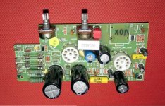
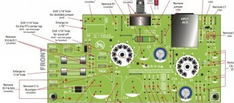
Thank you, Printer 2. That was indeed a learning experience and I think I was able to follow your guide and understand a little more about schematics. Coincidentally, I had already downloaded the same images of that pcb on ebay. I'll upload them here for posterity. Also I'm uploading some helpful illustrations of the circuit board, which I found, iirc, on the Mercury Magnetics site. They helped make clear which section of the trace you are proposing to cut. A couple of further questions:
- The Ampmaker instructions say with the VVR you can choose to "vary the voltage to the whole amplifier or...only the voltage supplied to the power amplifier and keep the preamp at full B+ voltage". Is the latter installation the same as the one you describe, attached to the 470 ohm resistor?
- The Ampmaker instructions seem to suggest that further components are possibly required for the power section only installation, I've attached an highlighted. Is it safe to install the VVR kit on its own into the AC4TV or are maybe further components required?
- Most comments online say that the 'power section only' installation is best. If it's attaching the VVR to the resistor then I think I can do it but Ampmaker's instruction paint a more complex procedure, which makes me think it might be beyond my abilities. In which case I am toying with another two cheap solutions and I'd like to know what you think.
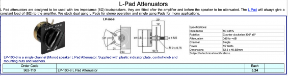
L-Pad - I've just been reading about replacing the AC4TV attenuator with an L-Pad. I think I could get a 8ohm 15w mono L-Pad for about £10 and this would be a straight swap. (possibly it wouldn't fit in the same space and I'd have to locate it somewhere else on the chassis)
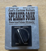
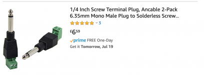
Power Soak - There's a Carl's Custom Guitar 8ohm 60w power soak going cheap locally. I could buy that, wire the amp output and speaker input into two 1/4 jacks and have it sitting in between. Maybe I could bolt it to the chassis. (From the look of the dial on the front of the soak though, it looks just like an L-Pad dial)
- The Ampmaker instructions say with the VVR you can choose to "vary the voltage to the whole amplifier or...only the voltage supplied to the power amplifier and keep the preamp at full B+ voltage". Is the latter installation the same as the one you describe, attached to the 470 ohm resistor?
- The Ampmaker instructions seem to suggest that further components are possibly required for the power section only installation, I've attached an highlighted. Is it safe to install the VVR kit on its own into the AC4TV or are maybe further components required?
- Most comments online say that the 'power section only' installation is best. If it's attaching the VVR to the resistor then I think I can do it but Ampmaker's instruction paint a more complex procedure, which makes me think it might be beyond my abilities. In which case I am toying with another two cheap solutions and I'd like to know what you think.
L-Pad - I've just been reading about replacing the AC4TV attenuator with an L-Pad. I think I could get a 8ohm 15w mono L-Pad for about £10 and this would be a straight swap. (possibly it wouldn't fit in the same space and I'd have to locate it somewhere else on the chassis)
Power Soak - There's a Carl's Custom Guitar 8ohm 60w power soak going cheap locally. I could buy that, wire the amp output and speaker input into two 1/4 jacks and have it sitting in between. Maybe I could bolt it to the chassis. (From the look of the dial on the front of the soak though, it looks just like an L-Pad dial)
Attachments
-
 Screenshot 2020-07-16 at 21.00.46.jpg98.7 KB · Views: 139
 -
 Screenshot 2020-07-16 at 21.00.58.jpg106.2 KB · Views: 167
 -
 PCB.jpg103.2 KB · Views: 454
 -
 pcb2.jpg77.6 KB · Views: 170
 -
 Screenshot 2020-07-18 at 17.57.06.png382.9 KB · Views: 118
 -
 Screenshot 2020-07-18 at 17.57.45.png453.5 KB · Views: 116
 -
 Screenshot 2020-07-18 at 17.58.08.png168.7 KB · Views: 136
After weighing up the options, taking into account the cost of an amp tech to install a circuit and the cost of an amp tech to fix my amp after I've tried to install a circuit, I've decided to go down the L-Pad solution.
I'm going to buy a Carl's Custom Speaker Soak or a TubeJuice Speaker Soak or, failing that, I'm going to buy a 15w 8ohn L-Pad, put it in a stomp box and connect between the amp and the speaker. I know, for many ears, this won't make for the perfect tone but I'm only just getting into playing the guitar again after many years away so I'm sure it'll be enough for me.
I'm going to buy a Carl's Custom Speaker Soak or a TubeJuice Speaker Soak or, failing that, I'm going to buy a 15w 8ohn L-Pad, put it in a stomp box and connect between the amp and the speaker. I know, for many ears, this won't make for the perfect tone but I'm only just getting into playing the guitar again after many years away so I'm sure it'll be enough for me.
I bought the TubeJuice Speaker Soak and I like it, it is useful in that it give you more options. It works best when literally attenuating the volume, taking 20% off the loudness. It means you can reach distorted sounds you'd never have achieved at 'bedroom' volume - which was my objective. But if you whack the amp's volume up to max, way beyond bedroom loudness it's still too loud with the attenuator taking off 20% but by the time you reach a bedroom volume the sound is too muddy and compressed. So don't dial in 100% on the amp and take it down 90% with an L-Pad attenuator and expect a great sound.
While writing this I've just realised that my TubeJuice is rated for 8ohms not the 16ohms of the AC4TV. Is this a problem? (I could fairly easily swap the L-Pad inside for a 16ohm version)
While writing this I've just realised that my TubeJuice is rated for 8ohms not the 16ohms of the AC4TV. Is this a problem? (I could fairly easily swap the L-Pad inside for a 16ohm version)