Where can I get small ferrite toroidal cores for switching transformers? I'm looking for something that will work for up to a 350W switching supply.
The most important question to be asked is "What Frequency?" This will determine what type of material is needed. If you are going to be running at 15-150kHz ferrites are the best types to use. However, there are many different types of ferrites to choose from. Magnetics is a manufacturer of excellent "soft" magnetic materials. www.mag-inc.com. If you cannot get small quantitites from them directly, then a distributor is Allstar magnetics. You also have to make sure that you minimize your core losses and balance them with your copper losses or the transformer will not give good performance. For a DC-DC converter make sure also that some sort of current-mode control is used to prevent the B-H curve of the transformer from going into the saturation region. If this happens you WILL loose you FET switches. GOOD LUCK!!!! I can provide guidance in this area if you so desire....
BeanZ
BeanZ
I will be running about 50kHz. It's for a DC-DC converter for a car amp. It's from ESP (where else?🙂 ). He gives a winding procedure for the transformer. He does not, however, say anything about layout, and he doesn't mention current-mode control and balancing of losses, so I will need some assisatnce in these areas.
Thank You.
P.S. When I tried your link, it said "You are not authorized to view this page"
Thank You.
P.S. When I tried your link, it said "You are not authorized to view this page"
For the uninformed, lower frequency gives higher efficiency buy higher frequency gives higher current density.
Of course if you don't get EMC compliance you will have the law after you...
Have a look at ETD43 or ETD49 size bobbins and cores. They're the '3055 of magnetics. Also 3C85 or 3C90 core material for 50 to 100Khz should be ok. Try and use schottky diodes for rectifiers if the voltage is not too high.
GP.
Have a look at ETD43 or ETD49 size bobbins and cores. They're the '3055 of magnetics. Also 3C85 or 3C90 core material for 50 to 100Khz should be ok. Try and use schottky diodes for rectifiers if the voltage is not too high.
GP.
Are you talking about toroids with the EM emitions? I thought toroids minimized that, and many, if not most car amps use them. I certainly couldn't use anything that emits EM noise, it will be within an inch of an audio amp.
SMPS are NOISY! quite a bit of the overall design effort of a SMPS often goes on measures to get the EMI/EMF under control.
AudioFreak is dead right.
Toroids are no quieter than any other and they are harder to wind. I make a living working as an engineer's dogsbody in a SMPS design lab all day every day. Believe me, SMPS's are NOISY .
Toroids are no quieter than any other and they are harder to wind. I make a living working as an engineer's dogsbody in a SMPS design lab all day every day. Believe me, SMPS's are NOISY .
SMPS are extremely noisy no matter what type of core you use. The noise will be much higher with an ETD style core because of the radiation which appears between the two halves. A toroid is commonly used because of its lower EMI but also because it doesn't require any additional hardware to mount (bobbin, etc). The weapon against EMI is containment. By enclosing the entire system inside a completely conductive chassis, it minimizes the magnitude of radiated energy. However, keep in mind that as the propogating E-Field hits the conductive chassis, it becomes a surface current and must have a low impedance path to a reference ground. In car audio, the small amount of noise which may be injected into the audio amplifier circuitry is acceptable only because the automobile is the noisiest audio enviornment possible....electrically and acoustically.
BeanZ
BeanZ
Use extensive filtering on the power line going into the amp. Otherwise the power line outside the amp will act as an antenna and radiate all around.
That and the low impedance chassis are probably the best ways to keep the EM radiation down.
/Marcus
That and the low impedance chassis are probably the best ways to keep the EM radiation down.
/Marcus
The design of the amp is such that the PSU is on a board right under the amplifier, really close to it. It looks like I should put an aluminum plate between the 2, I've been thinking about that for a while. Even at 60 Hz, we take measures to make sure noise doesn't get injected into the amp, at 50kHz...
Kilowatt said:
P.S. When I tried your link, it said "You are not authorized to view this page"
Try to remove the dot after com. There's a dot at the end by mistake.
http://www.mag-inc.com/
Here are some numbers on a toroid I just wrapped I wanted to see it's effectiveness running at other frequencies then it's design frequency.
It's was wrapped for 22khz.
6 turns on the primary of 6 28-gauge paralleled wires, 20 turns on the secondary of 6 28-gauge wires paralleled. All numbers were with a 220ohm load across the secondary coils. Wave generator gain is flat. Toroid is roughly 1"o.d. .6" i.d. hieght .25".
Curious thing is lines 8 and 9 say more power out then in which is impossible, or it is currently, and I'm wondering if my setup or test instruments are flawed some how. Or is there some kind of magnetic phenomena I don't know about that would create this incorrect read?
I'm using a standard pc based sine wave generator, Nch, out through an Sb-live sound card into a simple amplifier I built. Primary current read was done by breaking in between the transformer and one lead wire, secondary current read was done by putting the dmm in between on side of the 220ohm resistor and transformer. The current read is direct wire inside the dmm so there were not any losses there.
The voltage was read across the input and output points on the transformer with the 220 ohm connected for both primary and secondary reads.
I did the tests multiple times with 2 different dmm's with very close results.
Any thoughts.
Attachments
The numbers look right. The core probably doesn't handle the low 15kHz too well because it will force it into the non-linear or saturation region on the B-H curve. Those frequencies above the red numbers are due to losses. The core losses increase exponentially with frequency and copper losses will also increase due to the skin effect. If you are going to run a transformer at a higher frequency it is designed to run at a lower flux which also increases losses exponentially. Many transformers are designed to run at a Bmax of only 200 to 700G to minimize core losses. To do this more turns are required. There is a tradeoff that must be weighed because the copper losses will also increase. The skin effect can be minimized by making a single winding from several smaller wires in parallel but with the same total of copper area.
Another interesting thing that is sometimes overlooked is: Don't forget that when current is switched through the windings a voltage drop is lost across them due to series impedances of the wire. This voltage must be subtracted because it is not applied to the core. The same on the secondary side. What is the point? This could effect your turns ratio. If, with is voltage drop, makes the turns ration close to what you want the step-up or step-down voltage to be, the switching circuitry will operate at too high of a duty cycle. You don't want that.
BeanZ
Easyamp said:Here are some numbers on a toroid I just wrapped I wanted to see it's effectiveness running at other frequencies then it's design frequency.
It's was wrapped for 22khz.
6 turns on the primary of 6 28-gauge paralleled wires, 20 turns on the secondary of 6 28-gauge wires paralleled. All numbers were with a 220ohm load across the secondary coils. Wave generator gain is flat. Toroid is roughly 1"o.d. .6" i.d. hieght .25".
Curious thing is lines 8 and 9 say more power out then in which is impossible, or it is currently, and I'm wondering if my setup or test instruments are flawed some how. Or is there some kind of magnetic phenomena I don't know about that would create this incorrect read?
I'm using a standard pc based sine wave generator, Nch, out through an Sb-live sound card into a simple amplifier I built. Primary current read was done by breaking in between the transformer and one lead wire, secondary current read was done by putting the dmm in between on side of the 220ohm resistor and transformer. The current read is direct wire inside the dmm so there were not any losses there.
The voltage was read across the input and output points on the transformer with the 220 ohm connected for both primary and secondary reads.
I did the tests multiple times with 2 different dmm's with very close results.
Any thoughts.
The SB Live garbles any frequency output above 15kHz, so your measurements are not valid. Better use a decent sound card or a tone generator.
After reading your reponse I opened up my case only guessing that it was my sb-live but after seeing which card I was plugged into I realized my mistake.
You are right about the high frequency response of the sblive, I switch it in and attached my frequency counter and the sb-live actually doesn't go any higher then about 22khz although the cheaper and crappier (is that a word) Ess card goes all the way 60khz or maybe more, I haven't tested higher.
But the test's were done with my counter attached and the frequencies listed are all correct as for the other values thet must be close with respect to primary to secondary transfer efficiency.
There is something wrong with the test though, it maybe noise or lack of an equal up down wave, or the test setuo in genral, I don't know, but you can't have something for nothing. I'll look for a good wave generator or build one I guess.
Attachments
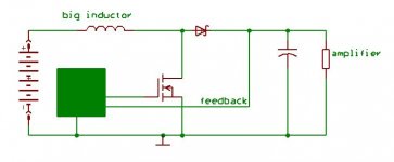
For a car amp you say... What about building a boost converter? Unless I'm missing something here, the secondary windings with a fixed turns ratio ratio seem like unnecessary complications. Do the secondary windings have to be isolated for your application?
Boost converters have several advantages: simplicity, efficiency, and flexibility. Assuming a suitable amplifier design, you could make it work with 2-ohm loads, 4-ohms, or 8-ohms or more with similar power output at each load by varying the output voltage. The green rectangle in the picture represents a boost regulator i.c., feedback resistors, and probably a couple of other small components to keep it happy.
Also, about what was said earlier: toroidal cores aren't the only type of core with low emissions, low-profile E-cores from Ferroxcube are also good (for high-current applications you can stack several of them alongside each other).
CM
Attachments
Easyamp,
what are you trying to do??
What is the ferrite material you are using or do you have any data on Al, Ae and max suggested B?
Be carefull berfore your soundcard is broken. 🙂
🙂
what are you trying to do??
What is the ferrite material you are using or do you have any data on Al, Ae and max suggested B?
Be carefull berfore your soundcard is broken.
🙂For a car amp you say... What about building a boost converter?
I have thought about using other topologies like charge pumps or inductor boost converters, but wouldn't you need to build two seperate pumps for positive and negative? This being my thought it seems easier to build a oscillator with some type of regulation for control, current amplifier, and a center tapped secondary step up coil.
what are you trying to do??
I'm just learning, and trying to figure out the smps's. But I guess once I 'm able to properly build my own I will use it as a psu in a car audio system, when I get a car.
What is the ferrite material you are using or do you have any data on Al, Ae and max suggested B?
It's just one I found on an old APC UPS board I salvaged so I don't know much about it. I do know it's important when calculating frequency and load as well as other stuff, to know what core your using, but I'm just experimenting.
- Status
- Not open for further replies.
- Home
- Amplifiers
- Class D
- cores