Hi,
I am using Ohmite brown devils [200 series] for Cathode bypass and for reducing voltage on the driver valve power supply circuit. The amplifier is a 211 and the power consumed is about 3.5W on each of the cathodes and driver valve circuit uses a resistor that consumes about 9W to drop 300V.
I am able to push air through with some convection and some from low noise fans that move air around the underside of the amplifier near the resistors so they can dissipate some heat BUT they are both placed near some potential complimentary heat sinks (Copper plate 3mm thick and large aluminium plate 19mm thick). Clearly these resistors are designed to be in free space but I can't help but wonder if it would be advantageous to use a direct contact also to the plates to take some additional heat away.
Any more useful thoughts from experienced amplifier builders?
Thanks,
Rich
Is there any problem with using heat-sink mounted resistors in the first place?

Always follow the mfr spec. Those are for free air, so use the mfr brackets.
Clamping them to a hard surface may cause cracking from thermal expansion, especially if uneven.
Clamping them to a hard surface may cause cracking from thermal expansion, especially if uneven.
Thanks for all the feedback. I already have the heat sink type and they get the chokes and output transformers pretty hot, the aluminium plate gets up to 55 Deg C, and when I try to measure the underside resistor with a laser gauge it seems pretty cool, which is good, but all the heat gets taken through conduction upwards to the top of the plate where the chokes and transformers are bolted.
I have got a fan assembly, and I am going to blow some air past the resistors, but I am now in agreement taking a little also by conduction to the plates is a stupid idea.
I am hoping free air with some air movement will prevent the plate/heat sink getting too hot, and spread the heat out a bit instead of conducting it all into the plate. and then into the output transformers and chokes.
Just an update for sharing outcomes for those who are interested.
I have yet to fit the fan assembly which I have ready to install, but in free air so far the Aluminium plate is nowhere near as hot (and passing heat into the chokes and transformers above).
Here are 2 comparative views from the underside of the amplifier (which is photographed upside down). The old one with a heat sink/transfer resistor and the new layout are free air resistors.
I will measure the temperature when the project is finished and I have installed the fans.
Rich
Perhaps some misunderstanding of how heat flows and what temperature is reached and where.
Post #6 says the aluminium plate reaches 55C. Is that with the amp in normal orientation (ie. not upside down or on its side), and dissipating normal power internally (eg. a class A amp), and is the ambient temperature normal for your location, and what was the ambient temp ? What heats up the aluminium plate - is it that 50W 10k resistor, or is it lots of other heated up parts under the plate, or ???
Did you measure the temperature of the choke and transformer outer skins at various spots?
You indicate you want to use a fan, but your description is ambiguous as to where the fan is and what air it will move. Will the fan be in an enclosed space under the aluminium plate, with no opportunity to vent to external ambient?
Perhaps show a photo of the amp itself.
My favorite approach are not winding ceramic resistors with integrated heatsink like to find in the image of post #7 but resistors without inductivity in a TO220 or TO247 outline (e. g. Caddock MP9100 or MP930).Is there any problem with using heat-sink mounted resistors in the first place?
https://www.caddock.com/online-catalog/current-sense/current.html
In certainly applications you will get better sonic performance than with winding ceramic 5W-10W resistors, e. g. in the ZEN single ended amp from Nelson Pass (0R47) but also in tube amps concerning the cathode resistor.
If the wanted value in ohms is not to find, serial and parallel mode of several ones are necessary.
Perhaps some misunderstanding of how heat flows and what temperature is reached and where.
Post #6 says the aluminium plate reaches 55C. Is that with the amp in normal orientation (ie. not upside down or on its side), and dissipating normal power internally (eg. a class A amp), and is the ambient temperature normal for your location, and what was the ambient temp ? What heats up the aluminium plate - is it that 50W 10k resistor, or is it lots of other heated up parts under the plate, or ???
Did you measure the temperature of the choke and transformer outer skins at various spots?
You indicate you want to use a fan, but your description is ambiguous as to where the fan is and what air it will move. Will the fan be in an enclosed space under the aluminium plate, with no opportunity to vent to external ambient?
Perhaps show a photo of the amp itself.
To help clarify.
ALL the temperature readings are with the amp in it's correct operating condition - playing music, sitting the correct way around on the shelf where it lives. I am not interested in the amplifier's temperature upside down!!
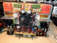
This is the amplifier in situ.
Yes I did measure choke and outer skins and they are 45-50 Deg C with the original heat sink resistor. Room temperature 23 Deg C in this case.
The main sources of heat to the underside of the plate are 3 heat sink resistors, the one I changed dropping 325V at 35mA. and others used for 2 DC heater resistors CRC circuit which are R82 at 3.25A. You can see these to the left on the image taken again from the underside.
The black capacitor PCB units on the left will be replaced by capacitors placed on one of the copper plate modules, as noted below - so more room for ai flow towards the R82 resistors.
The Fans will be from the underside pushing air upwards. This plate is shown in the correct orientation and has a 2 stage fan design, with temp sensor switch.
I am working on the amplifier and the bottom will be fixed with an underslung copper plate chassis system to take the additional components in a number of modules, one of these modules is a fan plate, this sits towards the left of the amplifier, just to the right of the protruding aluminium plate on the base. This is aiming at the underside of the DC heat sink resistors. I will also be changing these also to air cooled ones.
The air will exit through the top copper plates which have ventilation in them, and enter from below the amplifier supported of course by natural convection.
I hope this all makes sense<
R
tiefbassuebertr
Thanks for the guidance, I have not tried these.
My favourite resistors for sound quality atm are (in no particular order)
Ohmite WH series 5W
Ohmite 200 series Brown devil for larger W
Shinkoh 2W
Allen Bradley 2W (usually in parallel, with other resistor types and not in the direct signal path)
NOS IRC military metal film
There is a fairly noticeable improvement in the sound (fuller and more texture, richer in female voices) with the changes I made on the 10K, however I did also tweak the operating point of the 6c45 a little.
Rich
- Home
- Amplifiers
- Tubes / Valves
- Cooling resistors question