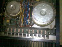
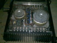
hi i have this pair of amplifiers originally intended for PA 100V system, its a 500W class B pull push through output transformer
I want to use it for class A amplifier.
Reasons.
Power supply, rectifiction wiring , chasis and Excellent heat sinks.
Input output connections all made.
Each amplifier has 2x10=20 TIP35C mounted and with drivers and emittter resistors.
since its a pull push both sides have 10 TIP35C NPN transistors and my plan is to use them like son of Zen with either resistive or acitve current sinks and get rid of output transformer (or may be could use for CLC filter) and also remove the input circuitry as it will be fed with fully balanced signals (as designed in son of Zen).
Problems. How to determine how much power can be extracted from the amplifiers , its a +34V single rail and there are two options either 4Ohm tap with minimum 2 ohm load or use the 100V line with minimum 20ohm load. The amp states its rated for 500W . As i understand 500W total would be 250W per side of pull push (10 TIP35C) and at 34 V rail its just about 7.5 ampere.
So if i have to bias the output stage through a 4 ohm emitter resistor to bring the emitter voltage at Vcc/2=34/2=17 volts i have to pass around 4 ampere =4ohmx4Amp=16V so it would be at the mid point and the quiscent current is half of what the amp can deliver at full RMS rating. Is this corrent.
Secondly as they are BJT in common collector mode how can i get voltage gain stage ??? can any one suggest any alteration from the current circuit diagram ??
Attachments
UPDATE
Ok.
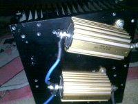
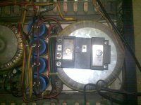
I have removed the primary inputs to output transformer from emitters of TIP35C and connected 4 Ohm 100W Dale resistors on emitter to ground.
I have adjusted the bias so the voltage at emitter is now 16V on each side of pull push driver so the current in each resistor is 16V/4ohm=4 amp with dissipation of 4*4*4=64W in each resistor and 64W in each TIP 36C bank so total dissipation is 128W per side and 256W total.
You can see that the toroid is prettty massive around 8 inch in dia and the smaller output transformer is around 4 inch in dia .
The floating differential voltage on both emitter resistors is OV fluctuates a bit.
I have not done listening tests as i am struggling to maintain bias steady because the voltage starts rising and i have to pull back the bias . i think i need to bolt the resistors with greater torque nuts on both sides.
any comments ?
Ok.
I have removed the primary inputs to output transformer from emitters of TIP35C and connected 4 Ohm 100W Dale resistors on emitter to ground.
I have adjusted the bias so the voltage at emitter is now 16V on each side of pull push driver so the current in each resistor is 16V/4ohm=4 amp with dissipation of 4*4*4=64W in each resistor and 64W in each TIP 36C bank so total dissipation is 128W per side and 256W total.
You can see that the toroid is prettty massive around 8 inch in dia and the smaller output transformer is around 4 inch in dia .
The floating differential voltage on both emitter resistors is OV fluctuates a bit.
I have not done listening tests as i am struggling to maintain bias steady because the voltage starts rising and i have to pull back the bias . i think i need to bolt the resistors with greater torque nuts on both sides.
any comments ?
Attachments
the heatsink looks quite thin.
Do you have any idea of the dissipation capability?
Now that you have 4A of bias current flowing, how hot will the transistors be after an hour or two of warm up?
What voltage is rising? Bias voltage across the emitter resistors?
or voltage across load resistors?
Load resistors may use a wire that has +ve tempco. If you keep pushing the same current through a PTC resistor then the voltage will rise.
you never fail to impress. YUP that happening.
The 4A 16V setting rises steadily......16.5-----16.8-----in about 10-15 minutes after which i shut it down to cool it.
Now i have made it 2A, 8V to try and it has shot up to 10.5V in about half hour......both terminals....but the differential floating is around zero.
Andrew the transitors heat sink is just luke warm i think never went above 35-40, some transitors are hot to touch though i assume around 50 but not more you can keep touching them..so the driver part seems ok to me...however the 4 ohm dale resistors are getting nasty hot and are not transfering heat to the heat sink...the heat sink is barely above room temprature... i have connected the resistors with just one screw on available holes and will get it to mill to get holes for both ends of resistor and tighten it with high torque nuts for better heat and mechanical coupling .
NOw the sound part.....just played it with my laptop sound card......its amazing fully balanced---single ended class A.......it was very very very warm....no complaints for sloppy bass...excellent depth ..pretty good highs just a a very faint hum and some very faint rf type whilte noise.... i think i need RF oscillation supression coil somewhere in the out put or ground coupling capacitor.
I have tested on my bookshelf Klipsch KG2.5 with 91 db sensitity , and although i have not made comparison A/B testing with my B&W 802--KRC HR Pre KRell---DAC MK4 Accustic arts ---Krell FPB 600 chain but i am pretty sure it will beat my system in terms of warmth and naturalness i really liked the involving mids.
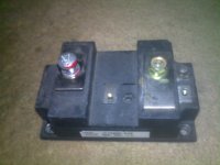
Now can any one suggest should i leave the project to resistive load or take up active current source....i have these module BJT rated for 400A, 2500W darglington modules mitsubishi.. and i can easily be made current sinks for each pull push pair...any comments on going active current sink rather than resistive loading of single ended class A .
The 4A 16V setting rises steadily......16.5-----16.8-----in about 10-15 minutes after which i shut it down to cool it.
Now i have made it 2A, 8V to try and it has shot up to 10.5V in about half hour......both terminals....but the differential floating is around zero.
Andrew the transitors heat sink is just luke warm i think never went above 35-40, some transitors are hot to touch though i assume around 50 but not more you can keep touching them..so the driver part seems ok to me...however the 4 ohm dale resistors are getting nasty hot and are not transfering heat to the heat sink...the heat sink is barely above room temprature... i have connected the resistors with just one screw on available holes and will get it to mill to get holes for both ends of resistor and tighten it with high torque nuts for better heat and mechanical coupling .
NOw the sound part.....just played it with my laptop sound card......its amazing fully balanced---single ended class A.......it was very very very warm....no complaints for sloppy bass...excellent depth ..pretty good highs just a a very faint hum and some very faint rf type whilte noise.... i think i need RF oscillation supression coil somewhere in the out put or ground coupling capacitor.
I have tested on my bookshelf Klipsch KG2.5 with 91 db sensitity , and although i have not made comparison A/B testing with my B&W 802--KRC HR Pre KRell---DAC MK4 Accustic arts ---Krell FPB 600 chain but i am pretty sure it will beat my system in terms of warmth and naturalness i really liked the involving mids.
Now can any one suggest should i leave the project to resistive load or take up active current source....i have these module BJT rated for 400A, 2500W darglington modules mitsubishi.. and i can easily be made current sinks for each pull push pair...any comments on going active current sink rather than resistive loading of single ended class A .
here are the darlington BJT power module picture
it can take 400A collector currrent conitnously...total Pd of 2500W.
I have 2 of these and would need 2 more for the other amplifier.
Should it be a good choice for current sink rather than resistors which i assume would give biasing problems of current stablility.
it can take 400A collector currrent conitnously...total Pd of 2500W.
I have 2 of these and would need 2 more for the other amplifier.
Should it be a good choice for current sink rather than resistors which i assume would give biasing problems of current stablility.
Attachments

oh did i mention that no speaker output coupling capacitor was used 🙂
some plans improvement.....using the secondary coil of out put transformer as CLC filter.
recifier diode noise cancellation with ceramic capacitors.
EMI filter for mains.
replacing the three 0.22uf electrolytic coupling capacitors with high quality metal film around 2.2 uF.
The active current source is under consideration subject to advice....
if you want to keep using those resistors, torque them down properly on both sides with cooling paste between resistor and heatsink.
No. the resistors seem not to like even 2A of current. after 45 minutes the emitter voltage i.e=4ohmx2Ampere=8V has risen to 12v meaning the current has risen to 3A.
I think either i would have to limit the current to 1 A using a 16 ohm resistor or go for active current source?
??????
I think either i would have to limit the current to 1 A using a 16 ohm resistor or go for active current source?
??????
Ok. Can i use an automotive 12V 65W car halogen lamp for resistive load.....has negative temprature coefficient....increasing current will increase resistance .....current would be self limiting.....rated at 14.4V but i assume would work at 16V easily...... no need of heat sinks....can easily take 4 A.
any ideas ???
any ideas ???
- Status
- Not open for further replies.
- Home
- Amplifiers
- Pass Labs
- converting PA amplifier into symetrical class A son of Zen