Top of the line yesterday receivers (without, or with broken hdmi inputs) are going to the recycling every day. This is really sad, given their huge, no longer produced power supplies, and their massive heatsinks. So much potential. I just cannot watch these being recycled or trashed. Just unethical waste. Example:

So I started buying them left and right, for 1/100 of their original cost. Been gutting them and putting cheap chinese amp PCB in there with impressive results.
But then I started thinking: These also came in some cases with elaborate amps, and real, first quality output transistors that simple cannot be bought on the chinese web sites. Then came the crazy ideeyer of using all those resources to build class A amplifiers? Some of them have state of the art input stages in their amplifier, even resembling the well known "blameless" topology. Their ouput transistors are guaranteed not to be chinese knock-offs. And their heatsinks are huge.
I want to try to convert one these amps to class A.
Shields down please and no "it can't be done", "they're not designed for that", etc... Hope are not made to be shattered.
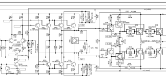
Case in point: In the following class AB schematic, the input stages are perfectly fine.
 I am seeking advice on how to take away and rewire one half of the output stages to change the (probably positive) side to a current source, possibly involving redesigning what is inside the red circle.
Please, let us waste anyone's time with how it cannot be done. I am seeking amplifier design advice on how to go about it with the least chances of failures.
And yes, I am aware of the voltage, current and power dissipitations issues. I will consider them off-topic. I am seeking help about the topology of the circuit, nothing else.
Thank you!
So I started buying them left and right, for 1/100 of their original cost. Been gutting them and putting cheap chinese amp PCB in there with impressive results.
But then I started thinking: These also came in some cases with elaborate amps, and real, first quality output transistors that simple cannot be bought on the chinese web sites. Then came the crazy ideeyer of using all those resources to build class A amplifiers? Some of them have state of the art input stages in their amplifier, even resembling the well known "blameless" topology. Their ouput transistors are guaranteed not to be chinese knock-offs. And their heatsinks are huge.
I want to try to convert one these amps to class A.
Shields down please and no "it can't be done", "they're not designed for that", etc... Hope are not made to be shattered.
Case in point: In the following class AB schematic, the input stages are perfectly fine.
Please, let us waste anyone's time with how it cannot be done. I am seeking amplifier design advice on how to go about it with the least chances of failures.
And yes, I am aware of the voltage, current and power dissipitations issues. I will consider them off-topic. I am seeking help about the topology of the circuit, nothing else.
Thank you!
Attachments


Wondering if it would be better to reduce the +- 55v rails be adding a pair of chokes before the rectifier and then bias farther into class AB instead. Also look at possibly increasing the .27 emitter degeneration resistors. After you get rid of all of the AV junk you should have room for that.
This is precious input. I was unaware there was a way to reduce the secondary AC. I need to look into this because, yes, I would prefer to work with lower voltages. I could then start playing more comfortably on the adventurous overbias playground. I have heard not so good things about overbiasing a class AB, but I am willing to experiment. Any idea how I should go about chokes?
Good to see you making use of these things. That top one could sink The Titanic. I have an Onkyo here, of the series that rapidly folded, leading to a lot of replacements and extended warranty. Lumpy great supply, reasonable caps to suit, though the heatsinks are not impressive looking things. http://bilder.hifi-forum.de/max/588...er-amp-stages-and-voltages-marked_1006636.png
I really don't want it, it's just fit for parts. UK though, so I couldn't post it
I really don't want it, it's just fit for parts. UK though, so I couldn't post it
Guessing this is a 4 channel amp going by the picture. I could be wrong on that for sure.
If you dropped the supply voltage by about 30% you could increase bias by 30% easily.
It would be useful to know what bias current is used on a stock unit. Likely some service manual will specify a voltage measured across the .27 ohm emitter resistors.
Some of these can be biased right on the edge of crossover distortion and you will notice if they are under biased.
The first option I would use would be choke input filter see https://www.diyaudio.com/community/threads/how-to-design-a-choke-input-filter.385661/
The typical capacitor input filter will result in a supply voltage that is about 1.3X the transformer voltage. Choke input would be about .95X the transformer voltage.
In the case of the normal split supply you could put a pair of chokes between the transformer and rectifier. You would not need gapped cores in that case. My guess is you would want about 5-10mh 5-10A roughly.
Some advantages of choke input over capacitor input is supply regulation versus load is somewhat better. The other is ripple current on the supply capacitors will be somewhat less.
Less ripple current can mean less heat and longer capacitor life.
Other option is to get a bucking transformer and drop the line voltage and supply by about 30%. Then bump your bias 30% higher and see if you notice.
If you have a variac you could drop the line voltage and bump up your bias.
It is actually a 7-channel amp, you see 4 amps on the left heatsink, and the 3 on the right heatsink are not obvious. This monster is rated at 11 Amps as per the rear panel and weights over 60 pounds.
I have considered running the primary through another transformer dropping voltage by 30-40%, but I am affraid I would lose current capacity by serializing them. Again, may be not, I should experiment. But that big toroidal is sooo beautiful, would I dare defile it.
I have considered running the primary through another transformer dropping voltage by 30-40%, but I am affraid I would lose current capacity by serializing them. Again, may be not, I should experiment. But that big toroidal is sooo beautiful, would I dare defile it.
Depending on the power supply transformer cosntruction, it might be possible to remove some turns from the secondary without tearing it apart and achieve the desire voltage.
About the chokes: 10mH smothes peak current and provide a good voltage reduction.
Just simulating the V+:
No chokes:


With chokes


About the chokes: 10mH smothes peak current and provide a good voltage reduction.
Just simulating the V+:
No chokes:
With chokes
Guessing the unit has about +- 50 volts for the output and 55 for the driver.
Really I have just seen some recap jobs on class A amplifiers where capacitor life could be extended.
I know the case can be hot and age just gets them but reduced ripple would not hurt capacitor life.
Really I have just seen some recap jobs on class A amplifiers where capacitor life could be extended.
I know the case can be hot and age just gets them but reduced ripple would not hurt capacitor life.
In addition to or in lieu of using choke input power supply, you could also use simple switching buck converters to make whatever regulated lower voltage you may want (ie +/-35V). This has the advantage of turning excess voltage into extra current capacity. You can get full VA rating from the transformer. This and the reduction of ripple may be a big deal for a fully class A amplifier.
The amps themselves are very likely better then the Chinese replacements. 7 channels allows for bi amps and subwoofer.
You need to build a splitter and preamp board to replace the AV board.
You need to build a splitter and preamp board to replace the AV board.
Thanks all for your interest.
As to the switching power supplies, I am of the ones who believe they still introduce too much electrical and magnetic noise for high-end audio. Besides, those massive analog transformers are free... But you are right about efficiency. I am looking at under-using those big supplies so they remain where they are closest to the ideal voltage source. I will also experiment with voltage regulators. Hey, why let those output transistors go to waste?
As to reusing their current amp boards, first because they have to fit 7 of them in a tight space and budget, they are designed with less than perfect topology and current sources, cost in mind, they have debilitating current limiters, and use single sets of outputs. (Except for the exception in my first post, an HK AVR-7200) My plan is to experiment with MOSFETS, class A, may be a blameless design, all with parallel output transistors. Plus, I think bi-amping off the same power supply kind of defeats the purpose... I'd rather build a monoblock for my subs. But you are correct about the quality of the output transistors, wich is why I will probably toss the chinese output transistors and reuse the stock one.
Now, as to whether the transformer can be wired for 220, I have considered it, but that would turn into +-25-30VDC, which is not sufficient. Except may be for a class A.
50% loss, is hard to get excited about. I just saw the 30-40% and thought I would chuck the idea out there.
I think the smps idea wasn't to replace the transformers. I think it was to lower the DC. Converters in this voltage range cost peanuts now. They might create another project cleaning the outputs though.
The chokes idea looks the most usable. It's low frequency, so some might say a laminated core is better, cheaper, and what the transformer is anyway.
Indeed, I have considered the simple buck converter to lower the DC, but that would also be a high-frequency switcher. I think chokes followed by the good ol' regulator is my most attractive option so far, lowering the voltage AND cleaning the ripple. Two birds stones in one shot.
This discussion is a bank of ideas for my experiments to come. Thank you all!
This discussion is a bank of ideas for my experiments to come. Thank you all!
Hello,
If the receiver has 5 or 7 channels, then not all pairs of transistors will be used in a class A amplifier. My spontaneous suggestion is to use unused transistors to make a power supply by adding a resistor and a zener diode. This will probably involve a lot of heat.
If the receiver has 5 or 7 channels, then not all pairs of transistors will be used in a class A amplifier. My spontaneous suggestion is to use unused transistors to make a power supply by adding a resistor and a zener diode. This will probably involve a lot of heat.
The linear regulator will produce heat. But the bias current required to stay in class A at lower rail is less, so the dissipation is reduced. And it it also split between the regulator and the output transistor(s). It will help you stay away from second breakdown, which starts rearing it’s ugly head around 40V on this transistor type.
With the heat sinking you have it's sufficient....Now, as to whether the transformer can be wired for 220, I have considered it, but that would turn into +-25-30VDC, which is not sufficient. Except may be for a class A.
You would need to cut the power supply voltage in half for class A. One way would be to turn the split 50 volts or so into just 50 volts and have an output coupling cap.
If the transformer has two secondary windings and the power supply has +-50V, then they are probably connected in parallel. You can try to connect the secondary windings in series, of course maintaining compliance so as not to short circuit. This should reduce the voltage by half and increase the current. Of course, I have not seen a diagram and I do not claim that this can be done in this case.
- Home
- Amplifiers
- Solid State
- Converting obsolete AV receiver to powerful class A amp?