Yes, another Leach amp. I have an old Nikko Alpha 230 that has served me quite well for many years. Last year, I plugged it in, turned it on, and choked on smoke. Fried output devices lead to a burnup on the driver board. I could get replacement Toshiba and NEC devices, but they are quite expensive. I decided to reuse te chassis and some other parts to make a Leach amp.
The original output devices (4 pairs of 2sc2565/2sa1095) were running at +-58.4V, so that should work. There are also secondaries for the driver section which used to run at 63.1V, but I will probably just tape those off. The toroid is shielded, which should be nice.
I will probably add to the existing pair of Marcon 15000uF 71V power supply caps. Do I need to for a stereo Leach amp (4 device)?
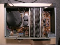
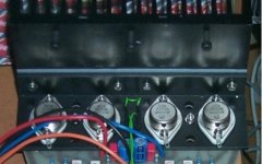
I really like to layout of the amp, which is much different from most of the designs I have seen. Power supply is on one side, driver board on the opposite side, power devices and heat sinks in the middle (see pic).
There is plenty of room for four devices on each of the two heat sinks. I am planning on putting two devices from each channel on each heat sink. Possibly putting two of the diode from each channel in each sink as well. I'll add a couple other pics in the next few posts.
Let me know what you think.
Thanks-
WAH
The original output devices (4 pairs of 2sc2565/2sa1095) were running at +-58.4V, so that should work. There are also secondaries for the driver section which used to run at 63.1V, but I will probably just tape those off. The toroid is shielded, which should be nice.
I will probably add to the existing pair of Marcon 15000uF 71V power supply caps. Do I need to for a stereo Leach amp (4 device)?
I really like to layout of the amp, which is much different from most of the designs I have seen. Power supply is on one side, driver board on the opposite side, power devices and heat sinks in the middle (see pic).
There is plenty of room for four devices on each of the two heat sinks. I am planning on putting two devices from each channel on each heat sink. Possibly putting two of the diode from each channel in each sink as well. I'll add a couple other pics in the next few posts.
Let me know what you think.
Thanks-
WAH
Attachments
Hi WAH,
I have two Alpha 230's at home, and a 220. Let me know how yours turns out. All of mine still work and are in storage now.
-Chris
I have two Alpha 230's at home, and a 220. Let me know how yours turns out. All of mine still work and are in storage now.
-Chris
Question for folks who have built Leach's:
I am planning on moving all the passives after the the output devices to a seperate baord that will mount just below the heat sinks. This way I can cut down the number of wires between the two, and I can just run the outputs to the speaker terminal block directly, which is one the opposite end of the amp from the driver boards (behind the power supply). I will also route power to the output device board before it goes to the driver boards, so I will need to put the decoupling caps on that board.
I know I am supposed to keep these wires as short as possible to prevent occs, but how long is too long? I want to use some amp connectors between the two boards, and the wires will be about 2-3 inches long. I will use one connector for power, one for left, on for right. Think I will have a problem with the connectors?
Thanks-
Brian
Also, I have leads for +12, +15 and +18V, and some free space. Anyone have ideas for add on goodies?
-Brian
-Brian
Hi WorkingAtHome,
The LowTim calls for 58V rails so you should be good. You don't say what the A is. Should be at least 6.
"I will probably add to the existing pair of Marcon 15000uF 71V power supply caps."
Considering their age, might be a good time to replace these with new caps. A pair of 25000uF/75V is a good investment in the future. Adding to the old ones might be a small problem. Lots of smarter people can tell you why.
You really must put the diodes on the heat sink with the transistors per the construction guide.
"wires will be about 2-3 inches long" is not going to be a problem.
Add on goodies:
Speaker protection circuit: http://sound.westhost.com/project33.htm
(altho I've never used one with the Leach amp 'cause it makes no pop on noises and Prof. Leach claims a dead transistor turns off the output of the amp to the speakers. Having intentionally shorted one out to find out, it seems to be true.)
Soft-Start Circuit from: http://sound.westhost.com/project39.htm
saves blowing fuses frustration.
Most all the transistors can be had as free samples from:
http://www.onsemi.com/site/MyON
When it's finished, you don't have to tell anyone that you replaced the boards.
Prosit
A pair of 25000uF/75V is a good investment in the future
Will do.
You really must put the diodes on the heat sink with the transistors per the construction guide
I plan on mounting them in the heat sink, similar to the way described, but since each pair of transistors will be on a seperate heat sink, I was wondering if I should arrainge them with all four between two tranistors, or two between each pair (wired the same of course).
Thanks-
Brian
Question about connectors
So, for the connections between my driver board and Output board, I want to use a connector. I won;t be passing +VCC and -VCC though the connector, just the transistor and diode connections.
I was thinking of Amp AMPMODU MT connectors: http://www.mouser.com/catalog/620/860.pdf
Does anyone think I will have problems with noise/capacitance/etc?
I would be using 22gauge wire.
Also, I am reworking the original boards to have a single stereo driver board (sort of a dual mono). I want to pass power in a single connection for both boards, and plan on using a standard 4 pin disk drive power connector for the power (+VCC, gnd, gnd, -VCC). I have a layout with a single power connector for both channels. Any problem with having asymetric power trace lengths other than resistance (I can make the traces nice and fat if needed)?
Thanks-
b
One more question:
I was thinking of wiring the output devices like this:
http://www.ampslab.com/Images/bi240drv1.jpg
Looks like they are using solid wire for DC. Should I do this or use tinned stranded? If I use solid, I would most likely use 14ga.
Thoughts?
-b
I was thinking of wiring the output devices like this:
http://www.ampslab.com/Images/bi240drv1.jpg
Looks like they are using solid wire for DC. Should I do this or use tinned stranded? If I use solid, I would most likely use 14ga.
Thoughts?
-b
Hi Brian,
All your questions are pertinent to building this amp and your concerns are quite valid. It would be a good idea to go to:
http://users.ece.gatech.edu/~mleach/lowtim/
Where Prof. Leach has all the documentation about successful building of this design. Download and print all the instructions and then study them quite closely. You will find that following the documentation leads to a first time turn on success. Every time I have had a failure on the boards was a result of taking shortcuts, not following instructions, bypassing testing procedures or dumb solder "misteaks".
As for
"Also, I am reworking the original boards to have a single stereo driver board (sort of a dual mono). I want to pass power in a single connection for both boards, and plan on using a standard 4 pin disk drive power connector for the power (+VCC, gnd, gnd, -VCC). I have a layout with a single power connector for both channels. Any problem with having asymetric power trace lengths other than resistance (I can make the traces nice and fat if needed)?"
Sounds as tho you intend to put both channels on one board? Power to it with one set of wires. Hmm, failure on one part of the board fries both sides of the amp and the output transistors, and the heat sink is a common ground. Are you sure you want to do that? But then perhaps I don't understand your intended topology.
Prosit
Hi Prosit-
I have read Prof. Leach's documentation. My circuit boards are based on his, just modified to move the output support devices (emmiter resistors etc) to a seperate board mounted below my heatsinks.
This is partly an attempt to fit an existing chassis, but more to have fun and create something new. I chose his design both for it's sound quality, but also because it has so much supporting documentation. It offers a lot of background and a solid platform to learn from. Far from a short cut, this is starting to take quite a long time to plan -- that's the fun bit.
I do plan to put both channels on one board, basically as two etchings of his (or my modified) layouts side by side. I could either run power seperately to each, or just tie then together from a common point on the driver board. Either way, they would eventually be tied together, either at the power supply or the driver board.
Maybe I am missing something there, but it seems as though there would be little difference. Not sure how that would lead to frying both sides of the board. Could you elaborate on that? Sounds like it would be quite the design flaw... ;-)
I will post a picture my board layout and a little diagram tomorrow.
Thanks for the feedback
-b
Hi Brian,
Only concerned that one fused power lead to both boards can be problematic. Separate fused power lines from the power supply to each board is safer and less likely to fry output transistors when a fault occurs on only one board. Been there, done that, got the t-shirt.
I've used the computer type power connectors like for a hard drive on several Leach amps with success. But I used 18 guage stranded wire with no problems. Like to see your pics. Been ever so happy with my Leach amps. One even runs my powered subwoofers, tho I did goose up the bias to 150 for a little more low end punch.
Prosit (German for "cheers")
Gotcha. I have trouble differentiating what I am thinkning and what I am writing.
So I whipped up this little diagram just now, and I think I see your point about the power, unless I add a third fused link just for the driver board, but why do that? So here I have two power connectors, one for each channel.
I am basing this layout on the layout of the Nikko, which I think I like, mostly because it's different.
The Nikko power was a little more interesting, in that the output board was powered by a rectifier and caps on the power board at +-58VDC. AC was passed to the driver board, which had it's own rectifier and caps, which resulted in 63.1VDC for the drivers, and also a 13.1 VDC for the op amp. Yikes.
There are also some low voltage taps off the transformer for turn on delay and power meters. I am ditching the power meters, and probably going to build a soft start circuit, mostly because I don't know the current rating of the transformer. I am assuming that since it was 120+W@8, that it will be okay. If the trandformer melts down, then I'll have to buy a new one, but maybe I won't need to.
Thanks for the help.
-b
Attachments
Mornin,
This guy has NIKKO ALPHA 230 Power Amp Service Manual
http://cgi.ebay.com/ws/eBayISAPI.dll?ViewItem&category=3280&item=5742522177&rd=1&ssPageName=WDVW
Might be a cool way to learn about the transformer specs so you can keep the power meters & turn on delay intact.
Have you looked at the doc's for the Leach Superamp also? Some good advice about mounting emitter resistors, etc.
Take a look at Klas Malman's Homepage
http://home.swipnet.se/malman/LeachAmp.html
for some other layout ideas.
Prosit
Hi-
I've got the service manual for the Nikko back when it first died. Nothing in there about the transformer other then the part number 🙁.
-b
I've got the service manual for the Nikko back when it first died. Nothing in there about the transformer other then the part number 🙁.
-b
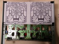
Okay, so I'm just about done with my board layouts. I based them on the original Leach design, but broke it into two seperate boards to fit my chassis.
Copper Trace side:
Copper Trace Side with Components (upside down):
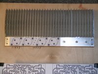
Pics of how the heatsink fits on:
Copper Trace side:
An externally hosted image should be here but it was not working when we last tested it.
Copper Trace Side with Components (upside down):
An externally hosted image should be here but it was not working when we last tested it.
Pics of how the heatsink fits on:
An externally hosted image should be here but it was not working when we last tested it.
An externally hosted image should be here but it was not working when we last tested it.
Two things.
Still trying to decide how to mount the heatsink diodes. As you can see, there will be two devices from each channel on each heatsink. The easiest thing to do would be to mount all four diodes from each channel on the first heatsin between the two devices there. Not sure if this will be adequate for tracking. I could also mount two diodes in each heatsink. Opinions on that?
I will probably need to add some more holes in the driver board to allow air flow.
Ooops, late, must go. bye.
-Brian
Hi Brian,
In the last pic, it looks like there are 2 heatsinks held together by your fingers. Judging from scale of your fingers, these heatsinks seem just a bit skinny for a leach amp without forced air flow. Is the base plate thick enough to put the diodes flush into it at the bottom? Not really a good solution 'cause the heat down there won't be even. Looks like you intend to use plastic transistors which are not as robust as TO3's.
Could you borrow and modify Klas Malman's mounting method?
http://home.swipnet.se/malman/LeachAmp.html
Prosit
Attachments
- Status
- Not open for further replies.
- Home
- Amplifiers
- Solid State
- Converting Nikko Alpha 230 to Leach Low TIM