Hello,
I am currently planning on bi-amplifying a pair of KEF C7's. I will take out the passive crossover and power the cones with some LM3886's amplifiers I have lying around. Before them, there will be an active crossover/preamplifier.
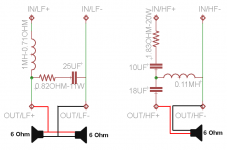
I am not sure on the details of how to accomplish all that, so I came here. As KEF states, those are 8 Ohm speakers crossed over at 2.500Hz. So I took out the filter and drawn it, attached is the schematic of it.
I took out the cones and measured their resistance without any filter. I had to use a plain multimeter to get their impedance as I haven't any LCR meter available. I read around 4.2 Ohm on both the tweeters and the midbass', so I can round it up and suppose all of them are 6 Ohm speakers, right?
I would like to draw the filter with some simulating software to see it response curve and to check (mainly out of curiosity) if that correlates with the 2.500Hz point that the manufacturer provides.
What I don't really know (I am quite noob regarding speakers/crossovers) is why they are labeled as 8 Ohm speakers while they don't have any, isn't it strange?. Even further, they have paralleled two 6 Ohm cones that gives 3 Ohm combined. Does the passive crossover make them appear as 8 Ohm's or something?
Then, the low pass filter seems to be a second order one, I think the high pass one should be of the same 2nd order but, it really is? isn't it a 3rd order one?
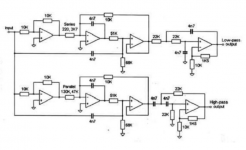
Then the next question should be, what active crossover topology to mount? I have seen those very nice boards to make it, seems to me the way to go. Their filter slope is 12dB/octave (it is a second order filter, right?), as far as I know for biamping a speaker I don't need to match the original slope so in theory I could make it be any order I would like, right? I have attached the schematic provided by the seller.
Line Level Active 2 Way Crossover Filter NE5532 PCB Only DIY Audiophile | eBay
Thanks!
I am currently planning on bi-amplifying a pair of KEF C7's. I will take out the passive crossover and power the cones with some LM3886's amplifiers I have lying around. Before them, there will be an active crossover/preamplifier.
I am not sure on the details of how to accomplish all that, so I came here. As KEF states, those are 8 Ohm speakers crossed over at 2.500Hz. So I took out the filter and drawn it, attached is the schematic of it.
I took out the cones and measured their resistance without any filter. I had to use a plain multimeter to get their impedance as I haven't any LCR meter available. I read around 4.2 Ohm on both the tweeters and the midbass', so I can round it up and suppose all of them are 6 Ohm speakers, right?
I would like to draw the filter with some simulating software to see it response curve and to check (mainly out of curiosity) if that correlates with the 2.500Hz point that the manufacturer provides.
What I don't really know (I am quite noob regarding speakers/crossovers) is why they are labeled as 8 Ohm speakers while they don't have any, isn't it strange?. Even further, they have paralleled two 6 Ohm cones that gives 3 Ohm combined. Does the passive crossover make them appear as 8 Ohm's or something?
Then, the low pass filter seems to be a second order one, I think the high pass one should be of the same 2nd order but, it really is? isn't it a 3rd order one?
Then the next question should be, what active crossover topology to mount? I have seen those very nice boards to make it, seems to me the way to go. Their filter slope is 12dB/octave (it is a second order filter, right?), as far as I know for biamping a speaker I don't need to match the original slope so in theory I could make it be any order I would like, right? I have attached the schematic provided by the seller.
Line Level Active 2 Way Crossover Filter NE5532 PCB Only DIY Audiophile | eBay
Thanks!
Attachments
Last edited:
This is a conversion to active speaker.
Bi-amping is connecting two amplifiers to the speaker terminals of one 2way speaker.
Bi-amping is connecting two amplifiers to the speaker terminals of one 2way speaker.
You don't have to duplicate the passive filters' transfer functions but that is probably the best way to get the result to sound decent if you aren't going to measure the response of the drivers. Stock crossover filters may or may not work well.
If you are going to measure the driver responses then you can use any filter you want and see if you do better than Kef with the drivers.
If you are going to measure the driver responses then you can use any filter you want and see if you do better than Kef with the drivers.
You don't have to duplicate the passive filters' transfer functions but that is probably the best way to get the result to sound decent if you aren't going to measure the response of the drivers. Stock crossover filters may or may not work well.
If you are going to measure the driver responses then you can use any filter you want and see if you do better than Kef with the drivers.
I haven't thought in measuring them, but should be a nice way to get into it now that I am getting into DIY microphones too. So I guess those kind of uncalibrated ones should be "good enough"?
http://www.diyaudio.com/forums/analogue-source/250749-diy-microphones.html
I think you got me wrong, the amplifiers and active crossovers would be in their separated enclosures, the speaker boxes would only contain the cones and the terminals. This, or I have a problem using the correct terminology...This is a conversion to active speaker.
Bi-amping is connecting two amplifiers to the speaker terminals of one 2way speaker.
Some in the USA refer to active speakers as bi-amped.
To help with differentiation I have suggested we call the two types:
active bi-amplification and passive bi-amplification.
But that seems to have fallen on deaf ears.
In the meantime Bi-amping is as I defined.
and
tri-ampling would be connecting three Power Amplifiers to the three sets of terminals on a 3way speaker.
To help with differentiation I have suggested we call the two types:
active bi-amplification and passive bi-amplification.
But that seems to have fallen on deaf ears.
In the meantime Bi-amping is as I defined.
Bi-amping is connecting two amplifiers to the speaker terminals of one 2way speaker.
and
tri-ampling would be connecting three Power Amplifiers to the three sets of terminals on a 3way speaker.
I haven't thought in measuring them, but should be a nice way to get into it now that I am getting into DIY microphones too. So I guess those kind of uncalibrated ones should be "good enough"?
http://www.diyaudio.com/forums/analogue-source/250749-diy-microphones.html
"Calibrated" using generic capsule response curves is better than not measuring. Better would be something actually calibrated.
Have you found Holm Impulse? It's free measurement program. There are all sorts of design programs out there that let you work on your filter transfer functions. I use Speaker Workshop, but most think it has a rather steep learning curve.
Andrew, I agree with your suggested terminology, and the OP has clarified that he wants to actively biamplify his speakers.
I haven't thought in measuring them, but should be a nice way to get into it now that I am getting into DIY microphones too. So I guess those kind of uncalibrated ones should be "good enough"?
http://www.diyaudio.com/forums/analogue-source/250749-diy-microphones.html
You're working with nice speakers, they really deserve a calibrated microphone. I got a very reasonably priced one from Cross Spectrum here in the states; but I'm sure there are places in Europe that offer them, too.
Andrew is correct. You used the wrong terminology, but we understood what you meant.This is a conversion to active speaker.
Bi-amping is connecting two amplifiers to the speaker terminals of one 2way speaker.
IMHO, Kef, as a company that build drivers with their own needs, probably markets speakers with a correctly designed crossover (look at the pretty unusual values of the components). That said, you probably need to replicate the passive transfer function to the active crossover. Problem is that without measuring the in-box frequency response and impedance of the drivers you're not able to find the transfer functions, as they are likely NOT a second order acoustical (as evidenced by the driver polarity). What most people here fall to understand is that a second order electrical filter merge with the driver/box characteristics and produce often a different acoustical order, and this is what you need to reproduce. Look here for an example: Zaph|Audio - ZA-SR71You don't have to duplicate the passive filters' transfer functions but that is probably the best way to get the result to sound decent if you aren't going to measure the response of the drivers. Stock crossover filters may or may not work well.
If you are going to measure the driver responses then you can use any filter you want and see if you do better than Kef with the drivers.
Ralf
Add a second order (2 pole) filter of the same frequency as the inherent roll off of the driver and you get a slower roll off but of fourth order (4pole).
If you spread the filter frequency away from the inherent, or natural, roll off of the driver you end up with a pair of cascaded 2 pole roll offs with a "weird shape" and that "weird shape" is probably not what you need.
It is generally accepted that what is required for good integration of two drivers is an acoustical roll off that gets very close to your theoretical "perfect" order roll off.
But to get this you must combine the natural acoustic roll off and the active filter roll off.
Then you have to include some EQ to correct for other response anomalies.
This EQ may interact with that "theoretical" roll off and require you revisit your active filter to counter the EQ correction. This is what they mean by "test and measure" the almost finished assembly.
Don´t overthink.
Build 2 amplifiers, say an LM3886 for the woofer, a TDA2030 for the tweeter, plus a 2500 Hz crossover (what KEF says is the crossover frequency) and send approppriate power and signal to each speaker.
Enjoy.
Build 2 amplifiers, say an LM3886 for the woofer, a TDA2030 for the tweeter, plus a 2500 Hz crossover (what KEF says is the crossover frequency) and send approppriate power and signal to each speaker.
Enjoy.
With a simplistic approach like that, it is highly unlikely the acoustical result would be better than the original passive crossover designed for the drivers.Don´t overthink.
Build 2 amplifiers, say an LM3886 for the woofer, a TDA2030 for the tweeter, plus a 2500 Hz crossover (what KEF says is the crossover frequency) and send approppriate power and signal to each speaker.
Enjoy.
Replicating the acoustic crossover the passive crossover currently provides is not very difficult with proper measurement tools (and the knowledge to interpret them) and a DSP.
Replicating the acoustic crossover the passive crossover currently provides with a home built active crossover is not at all easy, even with proper measurement tools and the knowledge to interpret them.
Thanks for all the input guys. I would like to say that I am not trying to make something extremely complicated, I just want to try and see if actively biamping is a good way to go.
While I highly appreciate all your tips, this is not the path I want to take, as if it were I would just build some good popular already tested design, with better drivers, etc. I mean, it would take far less time (and maybe even money) to have it done.
I don't want to invest more than some dollars on a microphone, so that route is discarded. Otherwise, as I said, I would just go with a proven pricey design instead of spending it on a mic that I will just use once or twice.
So we have to work "on the paper". I still have quite some doubts related to speakers design. As I said in my first post, isn't it a bit weird to have 6 ohms midbass connected in parallel?
Getting back to the xover, what king of topology are them? what are their filter slopes? I have been wandering around websites but didn't found anyone that looked similar.
Thanks
So, If I just connect my two amplifiers working with the same signal bandwidth to the two pair of terminals from my speaker (and keeping the stock passive crossover), that is passive bi-amping? and if I take out the passive crossover and make it active before de power amplifiers, that is active-biamping?Some in the USA refer to active speakers as bi-amped.
To help with differentiation I have suggested we call the two types:
active bi-amplification and passive bi-amplification.
But that seems to have fallen on deaf ears.
In the meantime Bi-amping is as I defined.
and
tri-ampling would be connecting three Power Amplifiers to the three sets of terminals on a 3way speaker.
Then I agree with you in using those terms, biamping while keeping the passive crossovers is what I called "fake biamping", which is nest to use only one amplifier 😀
Do what you like, but as weltersys said, just tossing together an active system without determining ing the correct crossover & EQ in an orderly manner will most likely be worse than the original.
Anyway, let's suppose I can get a nice calibrated mic. In that case, what are the steps to be taken in order to get.... whatever data I am looking for? And how to apply it to an active crossover? Could I take this approach if I use the PCBs I posted earlier?
If I already have a crossover schematic (as I posted), what prevents me to design a version of it but with active devices working at line level? I mean, there are very few components on the passive crossover, like 3 per channel, it can't be that difficult. From the point of view of the acustical and physics behaviour, wouldn't be the same without its drawbacks?
Thanks!
1) Learn about acoustical measurement, frequency and phase response.1)In that case, what are the steps to be taken in order to get.... whatever data I am looking for?
2)And how to apply it to an active crossover?
3)Could I take this approach if I use the PCBs I posted earlier?
4)If I already have a crossover schematic (as I posted), what prevents me to design a version of it but with active devices working at line level?
5)I mean, there are very few components on the passive crossover, like 3 per channel, it can't be that difficult.
6)From the point of view of the acustical and physics behaviour, wouldn't be the same without its drawbacks?
Thanks!
2) Learn about filter response and their phase response, and the difference between electrical and acoustic response.
3) To duplicate the acoustic response of the passive crossover will require a drastically different filter than the one you posted.
4) The requisite understanding of 1, 2 & 3.
5) The passive crossover components and the impedance response of the speaker in the box make for a very complicated LCR network that is critically tuned for a specific acoustic response.
If you think it is not difficult, you are in for a surprise when you start studying the TS parameters of a loudspeaker, which have very little in common with a resistor.
6) Active crossovers do have some potential advantages, but you would need to be at the level of the Kef engineers to implement them.
The old saying goes "if it ain't broke, don't fix it".
That goes double when you don't know how to fix it 😉.
This could be a start in your education of what is involved in a "simple" passive crossover:
http://www.diyaudio.com/forums/mult...designing-crossovers-without-measurement.html
Art
Last edited:
I reported my experiment, here and in the Tannoy users group, from about 30years ago on what you call "fake bi-amping" on a 2way speaker that only had one pair of terminals. This was such a success that I became an immediate convert............... biamping while keeping the passive crossovers is what I called "fake biamping",...........
I have used bi-amping on most of my systems many times since. I usually hear at least some improvement in sound.
I have tried active once (dcx24/96) and my extended experimented failed to even match the passive crossover version.
I have played with active low bass only speaker/s and this has proved a good avenue for improved sound.
I am currently trying again after a gap of about 3years, using a quite different topology. B1 as unity gain follower inside Sallen and Key 2pole filters.
Last edited:
The guys here are making things too complicated. The crossover inside the KEF is most likely a parallel topology filter - separate for mid and tweeter. Then just use it and connect LMamps' outs to appropriate filter ins. Both amps should get full signal.
A more smart way is to use a minidsp 2x4 for each speaker to act as line level crossover before the amps. But then you must get a microphone, measuring software and skill to use them. It is not easy and it takes at least a year to get the skill level to match KEF engineers. If you try to create an active crossover circuit by reverse engineering or own design, that does the same as minidsp, I guess it would take you some years to make it work well.
A more smart way is to use a minidsp 2x4 for each speaker to act as line level crossover before the amps. But then you must get a microphone, measuring software and skill to use them. It is not easy and it takes at least a year to get the skill level to match KEF engineers. If you try to create an active crossover circuit by reverse engineering or own design, that does the same as minidsp, I guess it would take you some years to make it work well.
So it will take years to duplicate to line level a crossover that has just 3 components?The guys here are making things too complicated. The crossover inside the KEF is most likely a parallel topology filter - separate for mid and tweeter. Then just use it and connect LMamps' outs to appropriate filter ins. Both amps should get full signal.
A more smart way is to use a minidsp 2x4 for each speaker to act as line level crossover before the amps. But then you must get a microphone, measuring software and skill to use them. It is not easy and it takes at least a year to get the skill level to match KEF engineers. If you try to create an active crossover circuit by reverse engineering or own design, that does the same as minidsp, I guess it would take you some years to make it work well.
Isn't anybody able to know the type of crossover used for both high and low pass? I mean the order, sallen-key, butterworth, etc...
- Status
- Not open for further replies.
- Home
- Loudspeakers
- Multi-Way
- Converting commercial speakers to bi-amplified