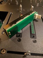
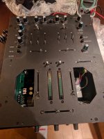
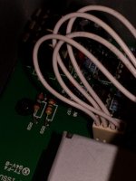
Have a Allen and Heath Xone 02 dj mixer. It's a 2 channel mixer, each channel stereo. I want to add pots to it to control each channels volume. I took it apart, The channel faders sit on a pcb, with 4 pin connector on it. What I don't fully understand is how the channel fader works with 4 wires, instead of the normal 6 wires that are standard on like a ALPS RK27. Can anyone help me make sense of that?

Mod note: Please upload images directly using the advanced editor instead of hotlinking to other sites, thanks!
Mod note: Please upload images directly using the advanced editor instead of hotlinking to other sites, thanks!
Last edited by a moderator:
Does it have fader start ? Perhaps it isn't analog but VCA controlled. Pioneer mixers and DJ consoles use VCA control. It's time to hunt the service manual.
It doesn't have fader start. From what I've gathered from various sites that have it listed for sale, they do seem to be VCA faders "Every fader is a deluxe VCA design, they’re all reversible, they all have contour controls and they can all be easily replaced by removing the steel faceplate.".
Is it that there is no L&R wired to the line fader? Rather it's just one input, output, but would the other two just be grounds? Also FWIW, I have briefly seen a dismantled Rane Empath Rotary version, that had ALPS RK27's each sitting on a pcb, but again only four wires coming out from that pcb.
Is it that there is no L&R wired to the line fader? Rather it's just one input, output, but would the other two just be grounds? Also FWIW, I have briefly seen a dismantled Rane Empath Rotary version, that had ALPS RK27's each sitting on a pcb, but again only four wires coming out from that pcb.
Attachments
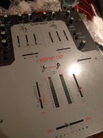
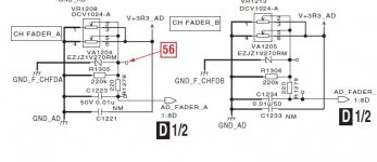
Reading the marking just below the line fader would have been another clue that it's a VCA fader 😉.
I believe those are stereo pots. You have 4+2 connections. 2 IN 2 OUT 2 Wiper
Remove the fader from the pcb or try to measure between pins actuating the lever to find out the pin-out, for each channel and then test with an identical resistance pot.
On a VCA, You usually vary a voltage on the pot, (3-5V) That goes to a microprocessor. So, on the molex there should be a fixed voltage on one or two pins. The wiper could be connected to one side, so it acts as a variable resistance and not as a regular pot. That leaves us with 4 connections 2 for each channel which You have on the connector.
Thanks for writing, I'm going to take the mixer apart again in the next few days. I will get back to you with progress.
Last edited by a moderator:
so I again had access to a rotary empath. this time I used a voltmeter to test for continuity on the pins on the alps pot and the connection going to the board. Only the front 3 pins are used! I think it's an input for the channel (both L+R), wiper, and ground. What do you think? If this is correct I only need a mono pot.
It's the same on the A&H, there are four wires going out to connection terminal but only three traces from the circuit board of the channel fader. I think I should be able to get by with a 100k rotary pot just fine.
I want to do a proof of concept. The A&H alpha fader pots have 0100knx2 inscribed inside the fader casing. So it's a 100k pot. I want to do a proof concept before I purchase a nice 100k pot to use in there. My question, can I test with a 50K pot?
Another idea I had in mind was to install a switch to be able to switch between the fader pot and the rotary pot. Would a DPDT be sufficient in this application?
Krank up the master mixer pot
What happens if You touch the connectors on the PCB with a finger ?
Leds begin to dance ? Humming ? Those are Your summing amp inputs. The others are the channel outs.
If nothing happens, I believe it's VCA controlled and a mono pot would make sense since it controls both channels. But for example the Pioneer Ergo uses stereo pots wired in parallel and is VCA controlled.
Attachments
Krank up the master mixer pot
What happens if You touch the connectors on the PCB with a finger ?
Leds begin to dance ? Humming ? Those are Your summing amp inputs. The others are the channel outs.
If nothing happens, I believe it's VCA controlled and a mono pot would make sense since it controls both channels. But for example the Pioneer Ergo uses stereo pots wired in parallel and is VCA controlled.
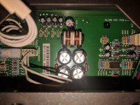
It's definitely VCA, no doubt about it. So, I poked around a bit and got it working. I wired in a spare stereo pot I had lying around. It seemed to work just fine, up until smoke started to come out of the mixer!! I toasted a resistor. I think it was because the pot I was testing with was 50k, instead of 100k. It all is working fine still, but will be swapping a new untoasted resistor.
So the way the stereo pot is wired three pins are used - input, output, and ground. If this is the case, and I want to switch between two potentiometers (one line fader and one rotary), can I only run the output of each to a SPDT switch, and run output of that to the mixer pcb? Does this make any sense? Input and ground pins would be wired from pcb to one pot, then to the other.
Attachments
- Home
- Live Sound
- PA Systems
- converting channel fader to rotary pot